
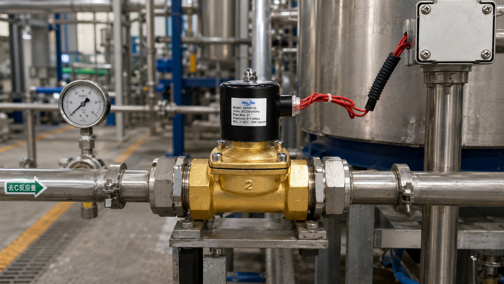
Yesterday, we shifted our focus to the microfluidic scale, analyzing the intricate mechanics of 2-way media-isolated solenoid valves and discussing how PEEK bodies and rocker membranes prevent sample cross-contamination in medical and analytical instruments. Today, we scale back up to gas systems to investigate a fundamental aerodynamic limitation that governs high-pressure pneumatic pipelines: Choked Flow.
When engineering a pneumatic circuit—such as rapid-cycle bottle blowing, automated air-clamping networks, or high-pressure gas venting—selecting a 2-way solenoid valve based strictly on pipe thread size is a recipe for system failure. Compressible fluids (gases like air, nitrogen, or argon) behave entirely differently than incompressible liquids under pressure.
As a gas forces its way through the restricted internal orifice of a 2-way valve, it follows strict thermodynamic laws. If the pressure differential across the valve crosses a critical threshold, the fluid enters a state known as choked flow, where further increasing the pressure drop will not yield a single additional liter of flow rate. Here is the aerodynamic breakdown of choked flow and how to mathematically size your 2-way valves around it.
1. The Physics of Gas Compression and Expansion
When an incompressible liquid passes through a valve orifice, its density remains constant while its velocity changes. When a compressible gas passes through that same orifice, its density, temperature, and pressure fluctuate simultaneously.
As upstream gas ($P_1$) enters the restricted orifice of a Normally Open or Normally Closed 2-way valve, it accelerates rapidly. The narrowest physical point inside the valve geometry is called the Vena Contracta.
As the gas squeezes through this bottleneck, its velocity approaches the localized Speed of Sound (Mach 1).
2. Crossing the Threshold: The Critical Pressure Ratio
Whether a gas reaches sonic velocity depends entirely on the ratio between the downstream absolute pressure ($P_2$) and the upstream absolute pressure ($P_1$). This boundary is defined by the Critical Pressure Ratio ($b$):
$$b = \left(\frac{P_2}{P_1}\right)_{\text{critical}} = \left(\frac{2}{k+1}\right)^{\frac{k}{k-1}}$$
Where $k$ is the specific heat ratio of the gas. For standard compressed air or nitrogen, $k \approx 1.4$, which yields a critical pressure ratio of:
$$b \approx 0.528$$
What this means in practice:
- Subsonic Flow (
$P_2 / P_1 > 0.528$
$P_2$
- Choked Flow (
$P_2 / P_1 \le 0.528$
3. The Consequences of a Choked Valve Orifice
Once a 2-way solenoid valve enters a choked flow state, a physical phenomenon occurs that surprises many maintenance technicians: the flow rate plateaus.
Because the gas molecules at the Vena Contracta are moving at the speed of sound, any structural changes, pressure drops, or expansions occurring downstream cannot communicate backward against the sonic wave front. The downstream pressure conditions are completely isolated from the upstream conditions.
If your valve is choked, dropping your downstream pressure further—even pulling a total vacuum ($P_2 = 0\text{ Bar}$) at the outlet port—will not increase the mass flow rate through the valve. The valve has reached its absolute aerodynamic ceiling. The only way to increase the mass flow rate at this stage is to drive up the upstream pressure ($P_1$) to pack more density into the gas, or to physically swap out the 2-way valve for one with a larger internal orifice diameter.
4. Modern Sourcing Standards: ISO 6358 vs. Standard $C_v$
Because gases compress, using standard liquid $C_v$ or $K_v$ equations to size a pneumatic 2-way solenoid valve creates massive margins of error. To resolve this, international procurement teams utilize the ISO 6358 standard, which defines a pneumatic component’s flow capabilities using two precise parameters:
- Sonic Conductance (
$C$
$\text{m}^3/(\text{s}\cdot\text{bar})$
- Critical Pressure Ratio (
$b$
$b$
Sourcing Metrics for High-Speed Pneumatic Venting
When auditing manufacturer catalogs for high-frequency or high-pressure gas distribution networks, ensure your pneumatic bills of materials mandate these parameters:
| Engineering Variable | Sourcing Requirement | Aerodynamic Justification |
|---|---|---|
| High-Volume Dump Lines | ISO 6358 Certified C and b metrics | Eliminates sizing guesswork; guarantees the valve can exhaust the vessel fast enough during choked states. |
| Seating Architecture | Poppet Style over Spool Style | 2-way poppet valves offer a direct, high-flow path with minimal internal restrictions, reducing premature choking. |
| Seal Compound | Polyurethane (PU) or NBR | High-velocity sonic gas streams can tear or pit soft elastomers; PU offers superior abrasion resistance against high-speed gas shearing. |
Conclusion
Pneumatic efficiency requires looking past localized pipe threads. In high-pressure gas loops, forcing a 2-way solenoid valve to handle an excessive pressure drop will inevitably lock the component into a choked state, choking your system’s overall throughput. By calculating your exact critical pressure ratios, prioritizing sonic conductance metrics over generic $C_v$ approximations, and specifying straight-path poppet mechanisms, you design your gas lines to manage sonic velocities safely and maintain optimal pneumatic cycle speeds.

