
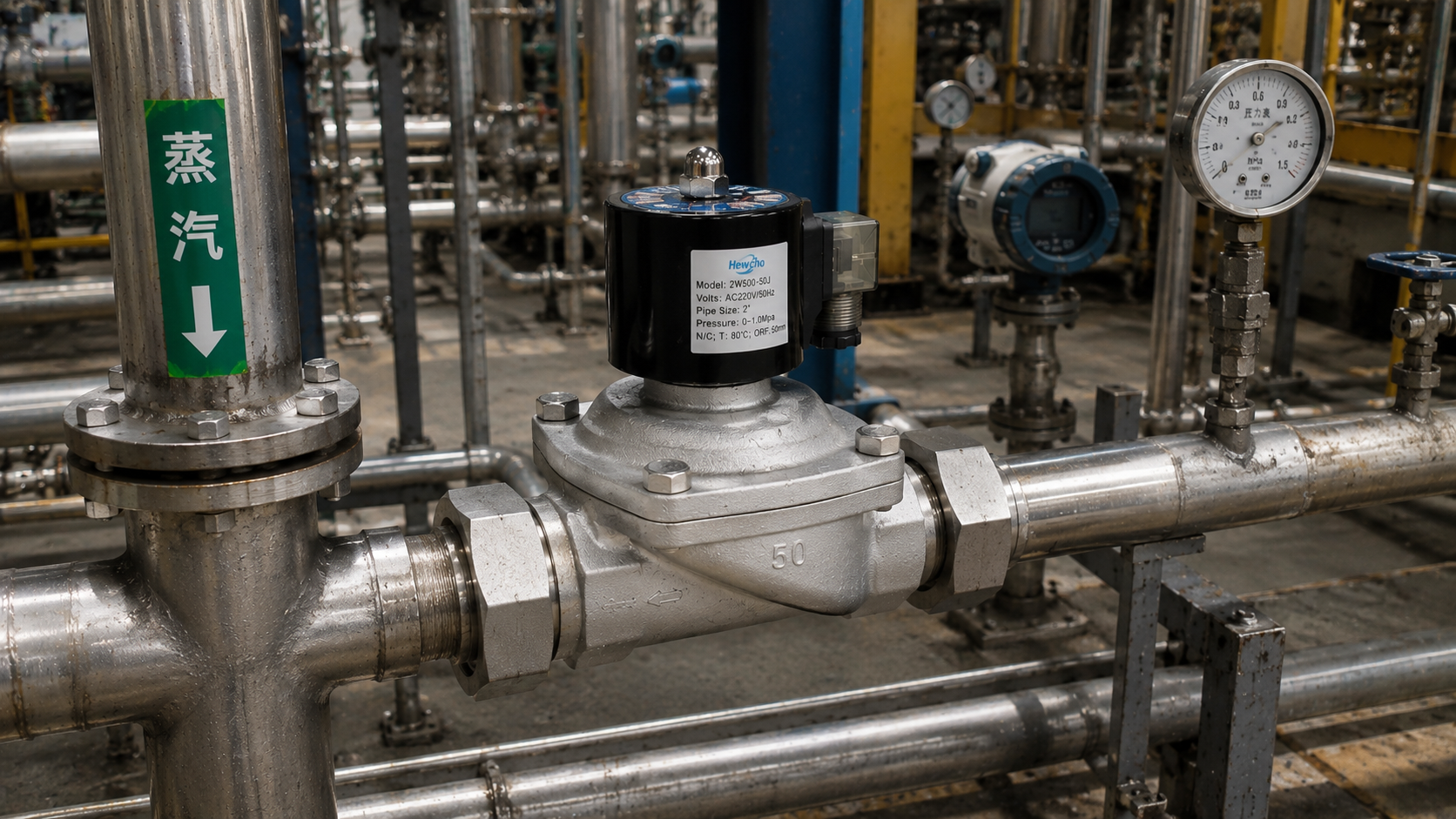
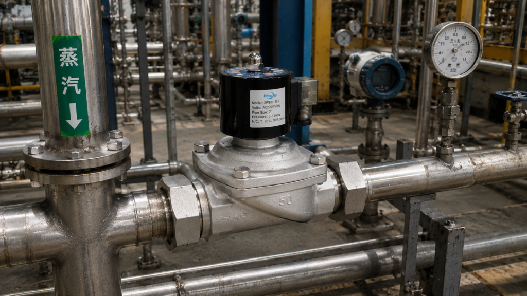
In our ongoing series exploring the engineering and selection of 2-way solenoid valves, we have extensively covered mechanical architectures, fluid dynamics, and seal materials. Today, we pivot toward a critical electrical phenomenon that frequently impacts industrial automation system design: AC Inrush Current vs. Holding Current.
When designing electrical control panels or specifying PLC output relays to drive Alternating Current (AC) 2-way solenoid valves, engineers often encounter premature relay failure or unexpected voltage drops. This issue stems from a failure to account for the unique inductive properties of an AC solenoid coil during its initial fraction of a second of activation.
Understanding this electrical spike is vital for building robust, long-lasting industrial control circuits.
1. The Electrical Transition: Inrush vs. Holding Current
When a 2-way solenoid valve utilizes a Direct Current (DC) coil, the electrical current rises linearly and remains constant throughout its cycle. AC coils behave entirely differently due to alternating magnetic fields and changing inductive reactance ($X_L$).
When an AC 2-way valve transitions from its resting state to its energized state, it experiences two distinct electrical phases:
- Inrush Current: The instantaneous spike in electrical current that occurs the exact millisecond voltage is applied to a de-energized coil while the internal steel plunger is still at its bottom rest position.
- Holding Current: The steady-state, significantly lower electrical current consumed by the coil after the plunger has successfully traveled up the armature tube and seated firmly against the core.
In premium industrial 2-way valves, inrush current can be 3 to 5 times higher than the holding current. For instance, a valve that draws only 0.4 Amps to stay open (Holding) may demand up to 2.0 Amps or more for a few milliseconds just to initiate the opening sequence.
2. The Physics Behind the Spike: Air Gaps and Inductance
Why does this dramatic electrical surge happen in AC coils but not DC coils? It all comes down to the changing inductance of the solenoid circuit as the internal mechanical components move.
An AC solenoid coil acts as an inductor. The total electrical opposition to Alternating Current—known as Impedance ($Z$)—is determined by both the wire’s raw resistance ($R$) and its inductive reactance ($X_L$).
$$Z = \sqrt{R^2 + X_L^2}$$
Inductive reactance depends heavily on the magnetic permeability of the core inside the coil.
- Plunger at Rest (Large Air Gap): When the valve is closed, the solid steel plunger sits away from the top core. This creates a large internal air gap. Because air has very low magnetic permeability, the coil’s inductance is at its absolute minimum. Low inductance results in low impedance (
$Z$
- Plunger Seated (Closed Magnetic Circuit): As that massive inrush current generates a powerful magnetic field, it forces the steel plunger upward. Once the plunger hits the top and seats against the stationary core, the air gap is completely eliminated. The magnetic circuit is closed through solid steel. This causes the coil’s inductance and impedance (
$Z$
3. The Burnout Risk: The Mechanical Jam Trap
Understanding the physics of the air gap explains the most common electrical failure mode of an AC 2-way valve: Coil Burnout due to Mechanical Stalling.
If a piece of rust, pipe scale, or debris enters the valve body and physically wedges the plunger so it cannot move, the air gap remains permanently open.
If the PLC commands the valve to open, the coil will draw continuous Inrush Current instead of dropping down to Holding Current. Because the coil is only engineered to handle that high amperage for a few milliseconds, it will rapidly overheat, melt the internal copper wire insulation, and experience a catastrophic short-circuit within minutes.
- Engineering Note: DC coils do not suffer from this specific failure mode; if a DC plunger is mechanically jammed, the current draw remains completely unchanged, though the valve will still fail to flow fluid.
4. System Sizing and Procurement Rules
To ensure your automated pipelines operate without electrical faults, circuit designers must implement three strict rules when sizing panels for AC 2-way solenoid valves:
- Size Relays for Inrush, Not Holding: If a 2-way valve spec sheet notes a holding power of 10 Watts (approx. 0.4A at 24VAC), do not size your PLC output relay for 0.4A. Look up the “Inrush VA” or “Inrush Amperage” and size your fuses, breakers, and solid-state relays to comfortably handle that initial multi-amp spike.
- Prevent “Chattering” via Voltage Stability: If multiple AC valves activate simultaneously on a weak power supply, the combined inrush currents can cause a temporary voltage drop. If the voltage drops below the minimum required to hold the plunger up, the plunger drops back down, triggering a cycle of continuous snapping open and closed—a phenomenon known as valve chattering that quickly destroys both the valve and the driving relay.
- Consider DC as an Alternative: If your facility requires tight control panel space with minimal fuse overhead, consider sourcing 24V DC 2-way solenoid valves paired with a robust digital power supply. While they lack the rapid-snap opening speed of AC valves, they entirely eliminate the challenges of managing multi-amp inrush current spikes.
Conclusion
A successful fluid control pipeline relies as much on proper electrical design as it does on metallurgy and seal compatibility. By correctly accounting for the inrush current dynamics of AC-powered 2-way solenoid valves, you prevent unexpected panel trips, safeguard your PLC modules, and protect your automated systems from premature thermal burnout.

