
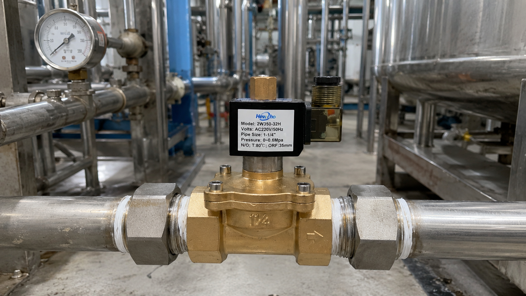
Yesterday, we shifted our focus to advanced metallurgy, executing a deep-dive analysis into the sub-atomic physics of hydrogen embrittlement and mapping out why high-nickel austenitic stainless steels and high-density PEEK seals are mandatory for high-pressure hydrogen infrastructure. Today, we transition from specialized gas chemistry back to environmental climate challenges, focusing on a widespread, costly weather hazard that routinely paralyzes outdoor industrial automation: Low-Temperature Condensation and Freezing.
In oil & gas tank farms, wastewater treatment plants, outdoor agricultural routing grids, and coastal pneumatic control panels, 2-way solenoid valves are continuously exposed to shifting meteorological conditions. While engineers frequently select weather-proof enclosures (such as NEMA 4X or IP66) to keep rain out, they often overlook a destructive thermodynamic threat generated from within the valve itself: internal dew-point condensation. When ambient temperatures plunge, this trapped moisture freezes, leading to jammed plungers, ruptured short-circuits, and immediate line failures. Here is the reliability framework required to diagnose and prevent condensation failures in outdoor 2-way solenoid valve networks.
1. The Thermodynamics of the Internal Dew-Point Trap
To understand how water appears inside a completely sealed, weather-tight valve, we must examine the interactions between ambient temperature drops and the valve’s operational duty cycle.
A standard 2-way solenoid valve coil generates significant thermal energy when energized. This heat radiates inward to the armature tube and outward to the surrounding air enclosed within the electrical conduit or junction box. This creates a pocket of warm, localized air capable of holding a high volume of water vapor.
The Phase Transition Sequence:
- The Shutdown Phase: When the automated system cycles the valve off, the electrical current drops to zero, and the coil begins to cool down.
- The Vacuum Draw: As the air inside the conduit or coil enclosure cools, it contracts. This volumetric contraction creates a slight internal vacuum. Despite IP66 or NEMA 4 gaskets, this micro-vacuum acts as a syringe, slowly sucking in humid ambient air through conduit threads, unsealed wire entries, or microscopic gasket imperfections.
- Crossing the Dew Point: As the night temperature drops toward the localized dew point, the warm, trapped air can no longer hold the moisture. Water droplets condense directly onto the coldest surfaces inside the assembly: the stainless steel armature tube and the copper coil terminal pins.
2. The Twin Failure Modes of Trapped Condensation
Once moisture condenses inside the 2-way valve assembly, it triggers two distinct mechanical and electrical failure sequences when freezing temperatures arrive:
Failure Mode A: The Frozen Plunger Seizure (Mechanical)
In a Normally Closed (N/C) 2-way valve, the condensed water wicks down into the ultra-tight 50\ \mu\text{m} clearance gap between the moving plunger and the internal guide tube walls. When the ambient temperature drops below 0^\circ\text{C} (32^\circ\text{F}), this water instantly freezes into solid ice, effectively gluing the plunger to the armature wall.
- The Resulting Burnout: The next morning, when the PLC sends a signal to open the valve, the coil’s magnetic field cannot break the ice bond. Because the plunger fails to lift and seat against the top core, the magnetic circuit remains open. In AC-powered valves, this open air gap forces the coil to pull continuous AC Inrush Current, driving temperatures up until the coil wire insulation melts and burns out within minutes.
Failure Mode B: Electrochemical Corrosion and Short-Circuits (Electrical)
If the condensation forms inside the terminal block or DIN connector plug, the water bridges the gap between the positive/live terminal and the ground pin. This triggers localized galvanic corrosion, eating away at the copper pins and creating a highly conductive path of carbon tracking. Eventually, this shunted current leak blows the control panel fuses or permanently damages the driving PLC output card.
3. Engineering Solutions for Outdoor Environmental Resilience
To ensure your automated pipelines operate flawlessly through severe winter weather and high-humidity cycles, your system architecture must incorporate three preventative design defenses:
True Hermetically Sealed Coils (Class H Encapsulation)
To entirely eliminate the vacuum-draw effect, outdoor 2-way valves should utilize fully encapsulated molded coils where the copper windings, internal wiring leads, and magnetic yoke are entirely embedded in a solid block of high-density, thermosetting epoxy or polymer. This architecture eliminates all internal air pockets, leaving absolutely zero space for moisture to collect or condense.
Explosion-Proof Breather Drains
If your 2-way valve utilizes a heavy-duty cast aluminum junction box or an explosion-proof (Ex d) enclosure, sealing the box completely can actually accelerate condensation. Instead, engineers install a stainless steel Breather Drain at the lowest point of the enclosure conduit run.
These specialized fittings feature an internal porous membrane or labyrinth path that allows trapped liquid water to drain out via gravity and permits the enclosure to breathe, normalizing pressure differentials while still maintaining the enclosure’s strict IP/NEMA weather-proof and explosion-proof integrity.
Space Heaters or Continuous Low-Voltage Trickle Current
For critical, zero-fail infrastructure (such as main facility safety shutoff loops), engineers keep the valve body warm during prolonged winter shutdowns using one of two methods:
- Enclosure Space Heaters: Installing a small, self-regulating PTC heating strip inside the localized valve control cabinet.
- Trickle-Current Heating: Programming the control system to feed a low-voltage, low-amperage Direct Current (DC) through the solenoid coil windings when the valve is in its de-energized state. This current is calculated to be too weak to lift the mechanical plunger, but high enough to generate a steady 2 to 5 Watts of purely thermal energy (I^2R), keeping the valve assembly safely above the environmental dew point.
Sourcing Specs for Outdoor Weather-Exposed Lines
When compiling engineering procurement documents for automated valves destined for outdoor, cold-weather regions, enforce these minimum thresholds:
| Technical Parameter | Sourcing Requirement | Reliability Justification |
|---|---|---|
| Coil Connection Type | Molded DIN Plug with Integrated Profile Gasket | Replaces loose conduit wiring; creates an airtight, IP65/67 moisture barrier over the electrical pins. |
| Environmental Rating | Minimum NEMA 4X / IP67 | Guarantees protection against driving rain, ice formation, and salt-air corrosion in coastal facilities. |
| Low-Temperature Limit | Rated down to -40^\circ\text{C} (-40^\circ\text{F}) | Ensures internal elastomer seals (like low-temp FKM or HNBR) maintain flexibility and don’t fracture when cycling in freezing conditions. |
Conclusion
Environmental isolation requires a deep understanding of phase-change thermodynamics. In outdoor automated processing loops, treating a weather-proof enclosure rating as a complete shield against internal moisture will inevitably result in frozen mechanical actuators and shorted electronics. By specifying fully encapsulated epoxy coils, integrating breather-drain filtration, and deploying active thermal regulation strategies, you insulate your 2-way solenoid valves from the invisible threats of dew-point condensation—guaranteeing smooth, uninterrupted process control across all seasonal extremes.

