
Yesterday, we investigated the thermodynamic challenges of outdoor winter environments, analyzing how internal dew-point condensation paralyzes mechanical plungers and detailing how fully encapsulated epoxy coils and continuous trickle-current heating guarantee sub-zero operational resilience. Today, we return to the internal fluid path to confront a critical design hazard in high-purity processing, chemical synthesis, and food-grade automation: Dead Volume and Fluid Stagnation.
When engineering fluid loops for semiconductor manufacturing, pharmaceutical batching, or sterile food and beverage dispensing, a 2-way solenoid valve must be treated as more than just a gatekeeper that opens and closes. It must be evaluated as a physical chamber within the pipeline.
Standard valve architectures inherently contain internal pockets, crevices, and dead zones where fluid can become trapped and completely isolated from the main flow stream. For process engineers, minimizing this dead volume is the single most important factor in preventing bacterial growth, cross-contamination, and purging inefficiencies. Here is the fluid dynamics breakdown of how to audit and eliminate dead volume in 2-way solenoid valves.
1. The Physics of the “Dead Volume” Trap
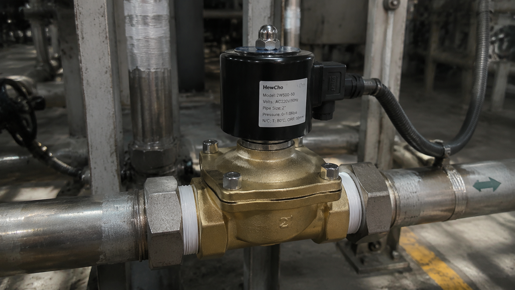
To understand where stagnant fluid hides, we must examine the internal geometry of a standard direct-acting 2-way globe-style solenoid valve.
When the valve is in the open position, fluid enters the inlet port, flows over the seat orifice, and exits the outlet. However, a significant portion of the fluid migrates upward into the armature tube (the guiding cylinder where the magnetic plunger slides).
This upper armature chamber represents the primary “dead volume” of the valve. Because it sits completely out of the direct, high-velocity path between the inlet and outlet ports, it experiences near-zero fluid turnover. This creates a series of severe process vulnerabilities:
- Bacterial Growth and Biofilms: In food, beverage, or biopharmaceutical lines, stagnant fluid trapped in the armature tube acts as a breeding ground for bacteria. Over time, these microbes form a resilient biofilm layer that continuously sheds contamination into the main product stream.
- Purge and Flush Failures: When a production line switches from Product A (e.g., a blue dye) to Product B (e.g., a clear fluid), the system is flushed with a cleaning solvent. Because the fluid velocity inside the armature tube is virtually stagnant, the old Product A remains trapped inside the valve head. It slowly leaches out over hours, ruining subsequent production batches.
- Particulate Precipitation: In chemical processes routing saturated solutions or slurries, stagnant fluid cools down or dries out within the dead zones, causing dissolved solids to precipitate out of suspension. These hard crystals then scratch the main elastomer seal, causing internal seat leakage.
2. Quantifying the Risk: The L/D Ratio
In fluid piping design, the severity of a stagnant pocket is mathematically evaluated using the Length-to-Diameter (L/D) Ratio.
$$\text{Stagnation Index} = \frac{L}{D}$$
Where L is the physical depth of the dead-end pocket or branch channel, and D is the internal diameter of that channel.
- The Danger Zone (L/D > 2): If the depth of a pocket is more than twice its diameter, the main fluid stream rushing past the opening lacks the hydrodynamic energy to penetrate the pocket. The fluid inside remains completely trapped, relying purely on incredibly slow molecular diffusion to mix with the main stream. Standard solenoid valves routinely possess an L/D ratio exceeding 3 within their armature assemblies.
3. Engineering Architectures for Zero Stagnation
To eliminate dead volume and achieve an uncompromised clean-in-place (CIP) capability, process engineers must abandon standard globe valves and specify specialized low-dead-volume configurations:
2-Way Diaphragm-Isolated Rocker Valves
As explored briefly in our analytical instrumentation review, Rocker Valves are specifically designed to minimize dead volume at the micro-scale.
By utilizing a flexible diaphragm that seals directly at the internal floor of a contoured plastic or stainless steel chamber, the entire armature tube is kept completely dry. The fluid is restricted to a shallow, sweeping lower channel. The internal geometry is curved and smooth, ensuring that the rushing fluid continuously self-cleans the entire wetted path with every cycle.
Coaxial 2-Way Valves (The Macro-Scale Standard)
For high-flow, high-viscosity industrial pipelines where micro-valves cannot handle the volume, engineers deploy Coaxial 2-Way Solenoid Valves.
As established in our heavy-viscosity analysis, a coaxial valve features a completely straight-through, unobstructed axial flow path. There are no upper cavities, no guide tubes filled with fluid, and no internal bends. The fluid acts as a continuous piston sliding through a tube, maintaining an L/D ratio of virtually zero within the valve body and completely eliminating any possibility of fluid stagnation.
Sourcing Specs for High-Purity, Low-Stagnation Lines
When writing procurement documentation or bills of materials for high-purity, sterile, or sensitive chemical routing networks, enforce these engineering metrics:
| Technical Parameter | Sourcing Requirement | High-Purity Justification |
|---|---|---|
| Maximum Internal Volume | Specified in Microliters (\mu\text{L}) or Milliliters (\text{mL}) | Allows process engineers to calculate the exact volume of solvent required to execute a 100% system flush. |
| Internal Surface Finish | Electropolished Stainless Steel (\le 0.4\ \mu\text{m}\ R_a) | Eliminates microscopic surface pits and scratches where bacteria or chemical residues can cling. |
| Drainability Orientation | Self-Draining Mount Configuration | Ensures gravity can fully empty the valve body when the pipeline is depressurized for maintenance or clean-down cycles. |
Conclusion
Purity is defined by internal fluid dynamics. In high-stakes manufacturing loops, treating a 2-way solenoid valve as a simple on/off switch ignores the hidden risks of fluid entrapment and localized bacterial growth. By calculating internal L/D ratios, migrating away from standard globe paths to diaphragm-isolated rocker or coaxial designs, and demanding electropolished wetted profiles, you eliminate fluid stagnation zones—guaranteeing pristine sample integrity and rapid, cross-contamination-free product changeovers.

