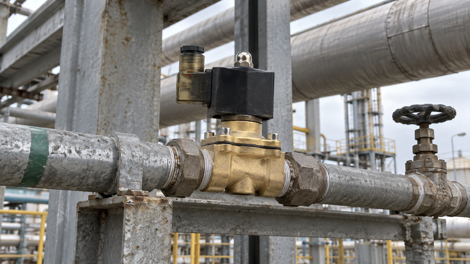
Pressure is one of the most important operating conditions in any automated fluid line. A solenoid valve may receive the correct electrical signal and still respond poorly when the pressure conditions do not match the way the valve is designed to work. This is why reliable selection and troubleshooting should begin with the complete pressure picture, including the upstream supply, downstream resistance, pressure difference across the valve, and changes that occur during startup and shutdown.
Industrial plants use solenoid valves to control compatible air, gas, water, liquids, and low viscosity oils. These applications can look similar from the outside, yet their pressure behavior may be very different. A compressed air line can lose pressure quickly when demand increases. A water line may experience surges when a pump starts or another branch closes. Understanding those changes helps engineers choose suitable equipment and helps maintenance teams diagnose faults without replacing good components.
Read the pressure at the right locations
A single pressure gauge does not always tell the full story. The most useful information comes from comparing pressure before and after the valve while the system is operating. Upstream pressure shows what the supply can deliver. Downstream pressure reflects the resistance created by pipe length, fittings, filters, equipment, and process demand. The difference between those readings is the pressure differential across the valve.
Record readings when the valve is closed, when it first opens, and after flow becomes stable. A gauge located far from the valve may miss a local restriction or a rapid pressure change. If the process is critical, use properly positioned instruments and confirm that they are calibrated. Pressure data should be recorded together with fluid temperature, flow demand, and the condition of upstream filtration. That context prevents a normal reading from being interpreted incorrectly.
Understand the operating method
Direct acting valves move the internal sealing element through the force created by the energized coil. They can be useful where the application requires straightforward control under suitable pressure and flow conditions. Other operating methods may use pressure within the system to assist movement. In every case, the actual working conditions must remain within the documented limits for the selected construction.
The safe position also matters. A normally closed arrangement blocks flow when electrical power is removed, while a normally open arrangement allows flow without power. The right choice depends on what the process should do during a power interruption. Pressure can remain trapped even after electrical power is disconnected, so isolation and safe pressure release procedures must be part of maintenance planning.
Watch for dynamic pressure changes
Static pressure measured during a quiet period may look acceptable even when the line becomes unstable during operation. Pump starts, fast closing manual valves, clogged filters, changing demand, and long pipe runs can create short pressure peaks or sudden drops. These events may cause delayed opening, incomplete closing, noise, vibration, or accelerated seal wear. They can also make a fault appear intermittent because the valve performs normally when the system is tested at low demand.
When symptoms occur only at certain times, compare them with pump cycles and nearby equipment operation. Observe the pressure gauge while the valve changes state, and check whether the downstream process creates back pressure. If rapid fluctuations are suspected, a suitable pressure logger may reveal events that an operator cannot see on a conventional gauge. Correcting the system condition is often more effective than repeatedly changing the valve.

Match materials to the medium and environment
Pressure capability is only one part of selection. The valve body and sealing materials must also be compatible with the medium, temperature, and surrounding environment. Brass and stainless steel bodies are commonly used for industrial fluid control, but the best choice depends on water quality, chemicals, corrosion exposure, connection method, and cleaning practices. Outdoor or washdown locations also need appropriate protection for the electrical enclosure and cable entry.
Common elastomer options include NBR, EPDM, and VITON. Each material behaves differently when exposed to water, oils, heat, acids, alkalis, or other chemicals. Compatibility should be checked against supplier guidance for the actual medium and temperature. A seal selected only by size may swell, harden, or lose elasticity, leading to leakage or slow response even when the pressure remains within the expected range.
Install for accurate and stable operation
Flush the pipe before installation so that metal chips, rust, scale, and excess thread compound do not enter the valve. Follow the indicated flow direction and support the pipe independently. Mechanical stress from misaligned fittings can distort connections and make sealing problems more likely. Place strainers where contamination is possible, and ensure that filters can be inspected without creating a difficult maintenance task.
Electrical checks should confirm the specified voltage at the coil while it is energized. Loose terminals, voltage drop, moisture, and damaged insulation can reduce operating force or create heat. During commissioning, cycle the valve under representative pressure and flow rather than testing it only with an empty line. Record upstream and downstream readings, response behavior, sound, external leakage, and coil temperature. These values create a baseline for future inspection.
Use pressure evidence during troubleshooting
If the valve does not open, first verify the control signal and voltage under load. Then confirm that upstream pressure is available and that the downstream line is not blocked. If the valve opens slowly or flow is weak, inspect filters, pipe restrictions, pressure differential, flow direction, and fluid viscosity. A correct electrical reading does not rule out a process problem.
If the valve does not close completely, isolate the system safely and inspect for contamination or damaged sealing surfaces. Check whether unexpected back pressure is holding the internal parts away from their normal position. Repeated cycling may temporarily move debris, but it does not remove the cause. Document the pressure readings and symptoms before disassembly so that the evidence remains useful.
Turn measurements into a maintenance standard
A practical maintenance record should include the medium, temperature, upstream pressure, downstream pressure, operating voltage, safe position, connection, body material, seal material, and inspection result. Trend these values instead of recording only pass or fail. A gradual increase in pressure loss may indicate a developing restriction, while a changing response time may point to contamination, wear, or unstable electrical supply.
Reliable solenoid valve performance depends on the relationship between the component and the system around it. When pressure is measured at useful locations, dynamic changes are considered, materials are matched to the service, and commissioning data is preserved, troubleshooting becomes faster and purchasing decisions become more accurate. The result is a fluid control system that is easier to maintain and more predictable in daily operation.