
Industrial solenoid valves are compact devices, but they sit at an important point between electrical control and fluid movement. A valve that suits the medium, line conditions, installation arrangement, and maintenance routine can make an automated process easier to operate. A valve chosen only by connection size or appearance may create avoidable trouble later. The most useful approach is to define the job clearly before installation and to keep the resulting selection record with the equipment.
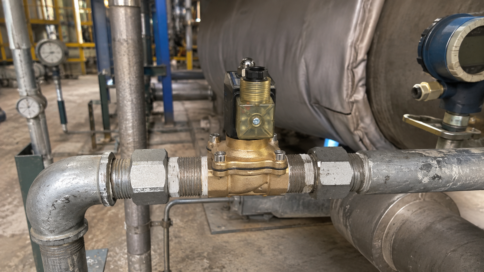
Start with the medium and the flow path
The first question is simple: what will pass through the valve? The catalogue covers options intended for water, air, gas, oil, steam, and other compatible process media, but compatibility must be assessed as a complete system. Fluid cleanliness, viscosity, temperature, chemical character, and the presence of suspended material all affect the decision. A valve used with a dirty line faces a different risk from one handling a clean, filtered fluid. When deposits or particles are expected, an appropriate upstream filter and a realistic inspection plan help protect the internal passage and sealing surfaces.
Flow demand is equally important. A connection that matches the pipe does not automatically deliver the required flow. The needed capacity depends on the operating differential, the fluid, and the purpose of the line. A small control duty, a larger process feed, a steam service, and a circulating water arrangement should be evaluated against their actual operating conditions. Record the normal condition as well as likely starts, stops, and low-flow periods. This gives the installer and maintenance team a more useful reference than a single nominal pipe description.
Match the operating principle to available pressure
Catalogue options include direct-acting and pilot-operated construction. Direct-acting arrangements are useful where the valve must operate without relying on a pressure difference across the main opening. Pilot-operated arrangements use the system pressure relationship as part of the opening and closing action, so the available differential pressure deserves careful attention. The correct choice is therefore connected to the way the line behaves, not merely to the desired on-off command.
Before selecting a valve, identify the pressure at the inlet, the expected pressure downstream, and how those values change during operation. A process that occasionally approaches very low differential conditions should not be treated in the same way as a consistently pressurized line. Pressure spikes, pump transitions, and downstream restrictions also deserve review. This discussion should include the people responsible for piping and control logic, because a sound valve selection can be undermined by an arrangement that creates unsuitable conditions at the valve.
Choose the normal state deliberately
Normally closed and normally open functions are both represented in the catalogue. The normal state is the valve position when the coil is not energized, so it should reflect what the process needs during a power interruption or control-system fault. A normally closed function can be appropriate where flow should stop when energy is removed. A normally open function may be suitable where flow is intended to continue in the unpowered state. The decision belongs to the process requirement and should be checked against the broader protection strategy.
Do not leave this choice to a last-minute wiring decision. Confirm the intended state with the process owner, then verify that the control drawing, valve marking, and commissioning checklist use the same language. This small discipline helps prevent confusion when equipment is serviced months after installation. It also makes functional testing more meaningful: the technician can confirm both the energized response and the intended unpowered condition.
Consider body and seal materials as a pair
Available body materials include brass, stainless steel, and plastic choices such as UPVC and CPVC. Each may suit a different environment, but body material alone does not establish compatibility. The sealing material, the fluid, the temperature, and the external atmosphere must be considered together. A material that performs well in a water line may not be the right answer for a chemically demanding duty, elevated-temperature service, or an exposed outdoor location.
Use the catalogue as the starting point for available construction choices, then compare the full wetted path with the process medium. When the duty is uncertain, document the unanswered question instead of assuming. This is particularly important for steam applications, where heat affects more than the valve body, and for installations exposed to weather, washdown, or corrosive surroundings. Proper support for piping is also valuable; excessive mechanical load can compromise connections and make later servicing harder.
Install for access, cleanliness, and correct direction
Good installation begins before power is connected. Check the flow-direction marking, clean the pipework, and remove installation debris before the valve is placed into service. Ensure there is practical access to the coil, electrical connection, and any part likely to require inspection. A valve buried behind rigid pipework may be difficult to diagnose even when the original selection was correct.
Electrical details matter as much as pipe details. Confirm that the supplied coil matches the available electrical supply and that the connection is protected appropriately for the installation environment. Keep wiring orderly and strain-free. During commissioning, cycle the valve while observing the actual process response, not only the control signal. Listen for abnormal operation, look for leakage at joints, and verify that the valve returns to its intended normal state when power is removed.
Build maintenance into normal operation
Solenoid valves benefit from a maintenance routine based on service conditions. The interval should reflect fluid cleanliness, cycling frequency, temperature exposure, and the consequences of an unexpected flow change. A practical routine can include visual checks for leakage, review of filters, confirmation of wiring condition, and functional cycling where the process permits. When a valve behaves inconsistently, investigate the surrounding conditions as well as the component itself. Restricted flow, contamination, incorrect pressure relationships, or electrical supply issues can produce symptoms that look similar.
Keep a concise record of the chosen function, materials, medium, normal operating conditions, and maintenance observations. This information supports faster troubleshooting and more consistent replacement decisions. It also makes future process changes easier to evaluate because the original assumptions are visible.
Conclusion
Reliable fluid control comes from matching the valve to the real process and then preserving that match through careful installation and maintenance. Start with the medium, flow requirement, pressure relationship, normal state, and material compatibility. Confirm direction, electrical suitability, access, and cleanliness at installation. With those foundations in place, an industrial solenoid valve can support predictable automated operation without relying on unsupported assumptions.

