
Industrial fluid systems depend on small control decisions that must remain dependable through thousands of operating cycles. A solenoid valve often sits at the point where an electrical command becomes a physical change in fluid flow. When that transition is clean and repeatable, a plant can manage water, air, gases, oils, and other compatible media with less waste and fewer interruptions. When it is neglected, a minor leak, delayed response, or contaminated passage can spread into a wider production problem. A practical operating routine therefore treats the valve as part of a complete process rather than as an isolated component.
Start with the working conditions
The first step is to record the real conditions around the valve. Confirm the fluid, temperature range, pressure range, expected flow direction, available voltage, duty cycle, and the cleanliness of the medium. These details determine whether the sealing materials, body materials, electrical coil, and internal passage are suitable for the job. A clear record also helps maintenance staff identify changes over time. If a line begins to carry a warmer fluid, develops more pressure fluctuation, or receives a different cleaning chemical, the original selection should be reviewed before performance declines.
Fluid compatibility deserves particular attention. A material that performs well with clean water may behave differently when exposed to oil, solvents, additives, or suspended particles. Compatibility is not only about whether a seal appears intact after installation. It also includes swelling, hardening, loss of elasticity, surface wear, and changes in friction. Consult the supplier documentation for the actual media and temperature range, then keep that information with the equipment record. This simple step prevents many avoidable substitutions during urgent repairs.
Make installation predictable
Good installation removes unnecessary stress from the valve. Flush the pipework before connecting the component so that cutting debris, rust flakes, thread sealant, and other particles do not enter the working chamber. Use the correct flow direction and allow enough clearance for inspection and coil replacement. Pipework should be supported independently; the valve should not carry the weight of a long or misaligned run. Tighten connections to a controlled level. Excessive force can distort threads or the body, while insufficient force can create a slow leak that becomes visible only after thermal cycling.
Electrical preparation is equally important. Check that the supply voltage matches the coil requirement and that the wiring is protected from moisture, vibration, and abrasion. A loose terminal may create heat even when the valve still appears to operate. Where the environment is wet or dusty, confirm that the enclosure and cable entry method are appropriate. Before full production begins, energize the valve in a controlled test and observe the sound, response time, and downstream flow. A short commissioning record gives the next technician a useful baseline.
Use a simple maintenance rhythm
Routine maintenance works best when it is divided into quick checks and planned service. During a quick check, look for external leakage, unusual noise, damaged insulation, loose fittings, corrosion, and changes in the normal operating response. Compare the current behavior with the commissioning record rather than relying on memory. A valve that still opens and closes may already be taking longer to respond or requiring repeated energization. Those early signs are valuable because they allow action during a planned window.
Planned service should include isolation of the line, safe release of pressure, inspection of the strainer or upstream filtration, and cleaning of accessible surfaces. If the design permits internal inspection, examine the passage and sealing areas for deposits or wear. Replace damaged seals with compatible parts and keep removed components for failure analysis when the cause is uncertain. After reassembly, repeat the leak and function checks. Record the date, medium, pressure, symptoms, work completed, and observations. A consistent record makes repeated failures easier to separate from one-time installation issues.
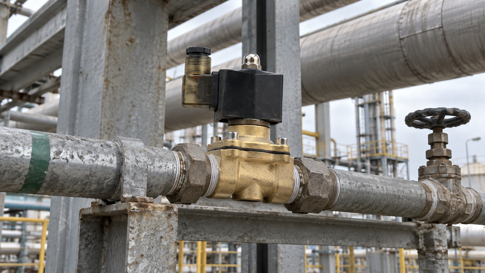
Diagnose symptoms in the right order
When a valve does not respond, begin with the process and electrical basics. Verify that the line is actually supplied, that the isolation points are open, and that the control signal reaches the coil. Check the voltage under load because a reading taken without the coil connected may hide a supply problem. If the coil receives the correct signal, listen for the normal actuation sound and inspect for excessive heat. A silent valve may have an electrical interruption, while a humming valve may be affected by unstable voltage, contamination, or mechanical resistance.
If the valve actuates but flow is weak or delayed, inspect upstream filtration, pressure differential, and the passage for debris. A changing pressure condition can also make a normally acceptable installation behave inconsistently. Check whether the fluid has changed temperature or viscosity and whether the actual flow direction follows the installation requirement. Avoid repeatedly cycling a suspect valve without finding the cause. Repeated cycling can increase wear and may move contamination deeper into the system.
Connect reliability with purchasing
Reliable operation is influenced by the way replacement parts are purchased. Keep a controlled record of the required connection, material, electrical supply, seal compatibility, and operating limits. When requesting a replacement, share the service conditions and a photograph of the installed arrangement, while removing any confidential plant information. Ask for documentation covering materials, test procedures, storage, and recommended maintenance. The goal is to make the next purchase a controlled engineering decision instead of a rushed visual match.
It is also useful to keep a small, clearly identified maintenance stock for critical lines. Store components in a clean, dry location and protect them from impact and extreme temperatures. Rotate stock according to the supplier guidance, and inspect packaging before installation. A spare that has been stored poorly can create the same delay as no spare at all. For high consequence processes, define an escalation path so that operators know when to isolate a line, call maintenance, or involve the equipment supplier.
Build a repeatable operating habit
A stable solenoid valve routine combines correct selection, clean installation, controlled electrical work, planned inspection, and evidence based troubleshooting. Each step is modest, but together they reduce unplanned downtime and make performance easier to predict. The most useful habit is to capture real operating information and feed it back into future maintenance and purchasing decisions. When operators, technicians, and suppliers work from the same record, the valve becomes a manageable part of the fluid system rather than an unknown source of interruption.

