
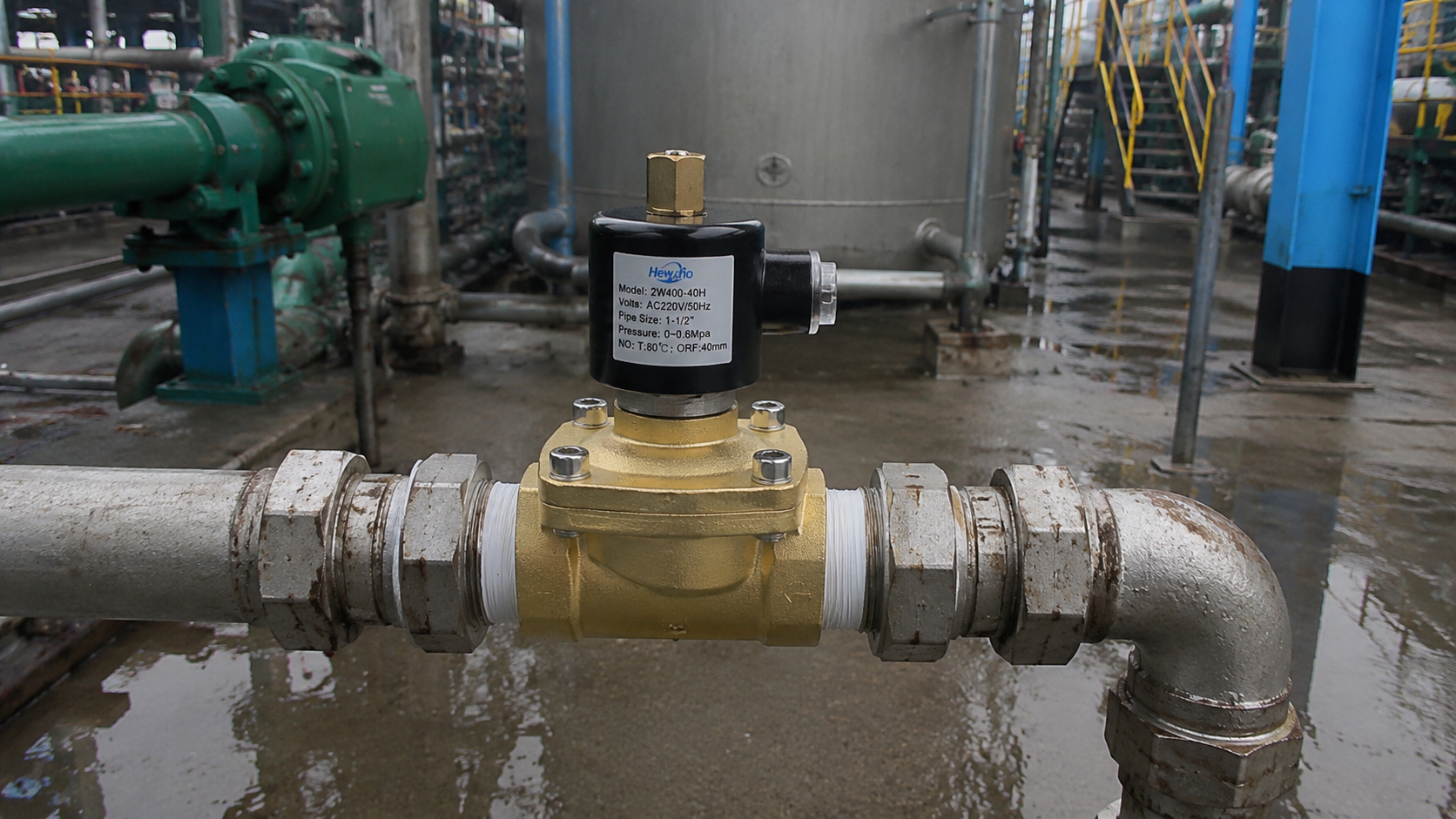
Yesterday, we took an in-depth look at predictive asset management, mapping out how real-time pressure drop ($\Delta P$) signatures can expose internal mechanical wear like wire-drawing and spring fatigue without shutting down the pipeline. Today, we return to foundational system architecture to resolve a classic engineering crossroads that dictates the footprint, power consumption, and reliability of your fluid network: Direct-Acting vs. Pilot-Operated 2-Way Solenoid Valves.
Selecting a 2-way valve based solely on line size and material compatibility is a common pitfall in system design. The internal mechanism chosen fundamentally changes how the valve interacts with system pressure. Failing to match this mechanism to your pipeline’s fluid dynamics can result in a valve that refuses to open, slams shut violently, or burns out its coil prematurely. Here is the mechanical and thermodynamic blueprint for specifying the correct internal valve architecture.
1. Direct-Acting 2-Way Valves: The Power of Pure Electromagnetism
In a direct-acting 2-way solenoid valve, the mechanical linkage is straightforward and robust. The moving ferromagnetic plunger is directly connected to the sealing disk or flap.
The Actuation Mechanics
When the valve is de-energized, an internal return spring pushes the plunger downward, pressing the sealing element against the valve seat orifice to isolate the fluid. When the coil is energized, it creates a powerful magnetic force ($F_{\text{mag}}$) that pulls the plunger straight up, lifting the seal off the seat and opening the flow path.
Key Sizing Constraints
Because the electromagnetic coil must physically lift the seal against the raw force of the upstream fluid pressure ($P_1$), the maximum operating pressure differential (MOPD) is strictly governed by the size of the internal orifice ($d$). The physical force required scales exponentially with the orifice diameter:
$$F_{\text{fluid}} = \Delta P \cdot \left( \frac{\pi \cdot d^2}{4} \right)$$
- The Zero-Pressure Advantage: Because it does not rely on fluid forces to move, a direct-acting valve requires Zero Minimum Pressure Differential (
$0\text{ Bar}$
- The Flow-Rate Tradeoff: To prevent the required coil size from becoming massive and power-hungry, direct-acting valves are physically restricted to small orifices (typically under
$6\text{ mm}$
$10\text{ mm}$
$C_v$
2. Pilot-Operated 2-Way Valves: Leveraging Pipeline Energy
When line sizes expand past $12\text{ mm}$ ($1/2\text{ inch}$) and fluid volumes surge, direct-acting coils become economically and physically unfeasible. Process engineers shift instead to Pilot-Operated (Indirect-Acting) architectures, which utilize the kinetic energy of the process fluid to actuate the valve.
The Actuation Mechanics
Instead of a rigid plunger, a pilot-operated valve utilizes a flexible elastomeric diaphragm or a floating piston as the primary sealing element. This diaphragm features a tiny bleed hole that allows fluid from the inlet to migrate above the membrane, balancing the pressure on both sides.
When the coil is energized, it doesn’t lift the main diaphragm. Instead, it opens a microscopic pilot orifice located in the center of the diaphragm. Because the pilot orifice is larger than the bleed hole, the fluid trapped above the diaphragm vents downstream faster than it can be replenished. This creates an instantaneous pressure imbalance:
$$P_{\text{underneath}} > P_{\text{above}}$$
This net upward force lifts the diaphragm off the main seat, opening the high-volume flow channel.
Key Sizing Constraints
- The High-Flow Benefit: Because the coil only needs to lift a tiny plunger to clear a miniature pilot hole, an exceptionally low-wattage coil can control massive, high-volume flows through pipe lines up to
$50\text{ mm}$
$2\text{ inches}$
- The Critical
$\Delta P$
$0.3\text{ Bar}$
$0.5\text{ Bar}$
Architectural Comparison Matrix
To optimize your automation bill of materials, evaluate your pipeline parameters against this fundamental mechanical matrix:
| Engineering Variable | Direct-Acting Architecture | Pilot-Operated Architecture |
|---|---|---|
| Minimum System Pressure | 0\text{ Bar} (No minimum required) | \ge 0.3\text{ Bar} to 0.5\text{ Bar} required |
| Ideal Application Scale | Low flow, micro-dosing, vacuums, sampling | High flow, high pressure, large bulk fluid transport |
| Orifice Sizing Limits | Generally small (< 10\text{ mm}) | Virtually unlimited (Up to large industrial flanges) |
| Response Time Profile | Ultra-rapid (5\text{ ms} to 20\text{ ms}) | Moderately damp (20\text{ ms} to 100\text{ ms} based on fluid viscosity) |
| Particulate Sensitivity | Low (Plunger can crush minor debris) | High (Microscopic bleed holes easily clog, stalling the valve) |
Conclusion
System automation efficiency requires precise mechanical allocation. In high-stakes processing loops, deploying a pilot-operated valve on a low-pressure gravity line or a heavily contaminated loop will trigger immediate operational failures. By accurately assessing your system’s baseline pressure differential, modeling required flow coefficients ($C_v$), and applying the correct actuation physics, you ensure your fluid network maintains uncompromised pressure isolation and clockwork operational reliability.

