
Choosing an industrial solenoid valve is easier when the discussion follows the process rather than starting with a component. The valve is an electrically controlled part of a fluid system, so its suitability depends on the medium, pressure relationship, required flow, normal state, materials, installation environment, and maintenance access. A clear checklist turns these factors into a repeatable selection method. It also gives operations, piping, electrical, and maintenance teams a shared record of the assumptions behind the installation.
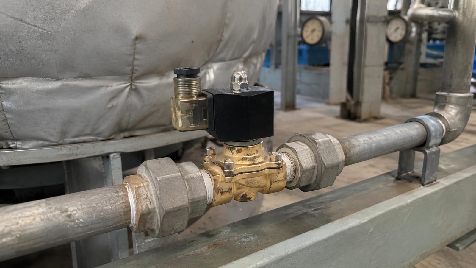
Describe the duty before comparing valve options
Begin by stating what the valve must do in plain language. Is it opening a water feed, isolating an air line, controlling a gas path, supporting an oil circuit, or serving a steam-related duty? The product catalogue covers construction choices for several common media, but the medium name is only the first part of the description. Note whether the fluid is clean or contains suspended material, whether it is likely to leave deposits, and whether the duty is continuous or intermittent. Temperature, chemical character, and viscosity can all affect the suitability of internal surfaces and seals.
Then identify the expected operating pattern. A valve that changes state occasionally faces different demands from one that cycles as part of a frequent automated routine. Include startup and shutdown behavior, not only the normal running condition. A system can behave differently after a pump stops, a vessel empties, or a downstream restriction changes. Capturing those conditions early helps prevent selection based on an overly simple snapshot of the process.
Review pressure conditions and flow needs together
Pressure information should show both sides of the valve. Record the inlet pressure, downstream pressure, and the likely difference between them throughout operation. The catalogue includes direct-acting and pilot-operated arrangements, and this distinction matters because their operating behavior is connected to the available pressure relationship. A direct-acting valve can be considered where operation must not depend on a pressure difference across the main opening. A pilot-operated construction should be assessed against the pressure conditions that will exist in the actual line.
Flow requirement deserves equal care. Pipe connection size is not a complete measure of usable flow. The required capacity depends on the medium, the pressure relationship, and the process objective. A line filling a vessel, a circulating water loop, and a small control point may have very different needs even when their piping looks similar. Discuss normal demand, peak demand, and any low-flow interval. Where the system conditions are uncertain, document the uncertainty and resolve it before the valve is placed in service.
Confirm the intended unpowered position
Normally closed and normally open functions are available in the catalogue. The selected normal state is the valve position when the coil is not energized, which makes it an important process and safety decision. A normally closed function may be appropriate when flow is expected to stop after loss of electrical energy. A normally open function may be appropriate when the process requires flow to continue in that condition. Neither choice is automatically better; the correct answer depends on the consequences for the equipment and the process.
Write the intended behavior in the control documentation and commissioning procedure. During testing, verify the response while energized and then confirm the return position after power is removed. This is more useful than checking for an audible coil response alone. Technicians should be able to relate the observed valve position to the process expectation without interpreting informal notes or relying on memory.
Assess materials across the whole service environment
Catalogue body choices include brass, stainless steel, and plastic materials such as UPVC and CPVC. These choices are part of the compatibility decision, not a substitute for it. Consider the body, seals, fluid, temperature, external environment, and connected pipework together. A material that is satisfactory for one water application may not be suitable for a hotter duty, a chemically demanding medium, or an installation exposed to weather and washdown.
Steam service needs particular attention because elevated temperature influences the whole valve assembly and nearby equipment. Outdoor or corrosive surroundings can create separate concerns for external parts and electrical connections. If the medium or environment has not been fully characterized, pause the selection rather than assume compatibility. A short, documented question at this stage is much easier to resolve than a leak or premature service issue after commissioning.
Plan the installation details that affect reliability
Installation begins with clean pipework. Flush or clean the system as appropriate before fitting the valve, and use suitable filtration when the line may carry particles or debris. Contamination can restrict internal passages and interfere with sealing, creating symptoms that may be mistaken for an electrical fault. Follow the marked flow direction and avoid placing unnecessary mechanical load on the valve through poorly supported pipework.
Access should be planned as deliberately as pipe routing. Leave room to inspect the electrical connection, confirm leakage at joints, and service components when the process is safely isolated. Verify that the coil and wiring arrangement suit the available electrical supply and the installation environment. During commissioning, operate the valve while observing the process result. Check for leakage, abnormal noise, unexpected delays, and correct behavior after de-energizing. These checks establish a useful baseline for later maintenance.
Turn the checklist into an operating record
After installation, retain a concise record of the medium, pressure conditions, chosen normal state, construction materials, installation date, and observed commissioning behavior. This record helps teams compare later symptoms with the original duty. It also supports orderly changes if the process medium, line pressure, or operating pattern is modified. Without the original assumptions, a replacement decision can become guesswork.
Maintenance frequency should reflect actual service conditions. Inspect for external leakage, review the condition of filters, check wiring and connections, and test function where the process allows. If performance becomes inconsistent, review the wider system before attributing the problem to the valve alone. Contamination, unsuitable pressure conditions, a blocked downstream path, and electrical supply issues can all influence the result. A methodical inspection is usually faster than replacing parts without a confirmed cause.
Conclusion
A dependable solenoid valve installation begins with a complete description of the process. Define the medium and cleanliness, pressure relationship, flow need, normal state, material compatibility, electrical supply, and access requirements. Use those facts to compare the available catalogue constructions, then verify the result during commissioning. With a clear checklist and a routine maintenance record, industrial fluid-control equipment can be selected and supported with practical discipline.

