
Slow response is an early warning that should be investigated before the process becomes unstable. The cause may be contamination, pressure change, fluid viscosity, seal condition, voltage drop, or mechanical loading. A step by step diagnosis prevents unnecessary replacement and preserves evidence that can improve future maintenance work.
Start with the actual process conditions
Reliable fluid control begins with a clear description of the service. Record the medium, pressure range, temperature range, flow direction, connection method, available electrical supply, and expected operating frequency. Air, gas, water, liquid, and low viscosity oil can place different demands on seals, body materials, and internal passages. A valve that works well in one utility line may require a different material choice in another.
Keep the service record with the equipment documentation. Process conditions often change after an expansion, cleaning program, pump replacement, or piping modification. When the information is visible to operators and maintenance staff, a replacement can be selected from evidence instead of from a rushed visual comparison.
Match the operating function to the safety plan
Determine whether the process needs flow to stop or continue when the coil is not energized. The safe position should be decided with the process owner and documented before installation. A drain, rinse, isolation, or cooling line may each require a different response during power loss. Electrical isolation does not remove trapped fluid pressure, so the safe position must be combined with a clear pressure release procedure.
Direct acting operation can provide a straightforward control arrangement when pressure, flow, and duty conditions are suitable. Check the documented operating limits before installation and confirm that the actual pressure difference across the valve is acceptable. Electrical compatibility by itself does not guarantee reliable movement.
Protect the passage from contamination
Most avoidable flow problems begin with contamination. Pipe cutting debris, rust, scale, thread compound, and cleaning residue can enter the valve during installation or later maintenance. Flush the line before connection and inspect upstream filtration at planned intervals. Where the medium carries particles, make the filter easy to isolate and clean so that maintenance does not get postponed.
Contamination can cause slow response, partial opening, leakage, noise, or repeated cycling. If a symptom appears intermittently, compare it with filter condition, pump operation, and recent work on the line. Cleaning the valve without correcting the source may provide only a temporary improvement.
Choose body and seal materials carefully
Brass and stainless steel bodies are common for industrial fluid control, but the right choice depends on water quality, chemical exposure, corrosion risk, temperature, and the surrounding environment. A wet process area, an outdoor skid, and a clean indoor utility cabinet do not create identical service conditions. Check the complete connection arrangement as well as the valve body, because mechanical loading and galvanic effects can shorten service life.
Seal materials such as NBR, EPDM, and VITON have different compatibility characteristics. Confirm the selected material against the actual medium and temperature. A seal can swell, harden, or lose elasticity even when the body appears undamaged. Record the material choice on the work order and include it in the replacement record.
Make installation repeatable
Support the pipe independently so that the valve does not carry the weight of a long or misaligned run. Follow the indicated flow direction and leave enough clearance for inspection and coil replacement. Tighten connections with controlled force. Excessive force can distort threads or the body, while insufficient force can create a slow leak that appears only after temperature cycling.
Electrical preparation deserves the same discipline. Confirm the supply type and voltage at the coil under load. Protect terminals and cable entries from moisture, vibration, chemical splash, and abrasion. During commissioning, operate the valve under representative pressure and flow, then record response time, sound, leakage, downstream flow, and coil temperature.
Use a logical troubleshooting order
If the valve does not respond, begin with the process and electrical basics. Verify that the line is supplied, isolation points are open, and the control signal reaches the coil. Measure voltage under load because an unloaded reading can hide a weak supply. If the coil is energized, listen for the normal actuation sound and check for abnormal heat.
If the valve actuates but flow is weak, inspect the upstream filter, pressure difference, flow direction, pipe restrictions, and fluid viscosity. If the valve does not close completely, isolate the line safely and inspect for contamination or damaged sealing surfaces. Avoid repeated cycling without identifying the cause, because cycling can move debris deeper into the working area.
Turn maintenance records into better decisions
A useful record includes the medium, temperature, upstream pressure, downstream pressure, operating voltage, safe position, connection, body material, seal material, inspection result, and work completed. Record symptoms in plain language and compare them with the commissioning baseline. Trends are more useful than isolated pass or fail notes. A gradual response change may reveal contamination, wear, voltage drop, or an altered process condition.
For critical lines, keep compatible spares in a clean and dry location. Protect them from impact, moisture, and extreme temperatures, and inspect packaging before installation. When a replacement is needed, share the service conditions and a photograph of the arrangement with the supplier. This creates a traceable engineering decision and reduces the chance of installing an unverified substitute.
Review the result after service
After an inspection, adjustment, or replacement, allow the line to return to normal operating conditions before closing the work order. Observe the valve during more than one cycle and compare the result with the commissioning baseline. Confirm that pressure, flow, electrical response, sound, and external sealing are stable. If the process includes cleaning or temperature changes, observe the equipment again after that step because some problems appear only when the line changes state.
Capture the final condition in the maintenance record and note any follow up action. A clear record should tell the next technician what was observed, what was changed, and what evidence supported the decision. This habit reduces repeated investigation and helps the plant plan spare parts, filtration work, electrical checks, and future inspections with greater confidence.
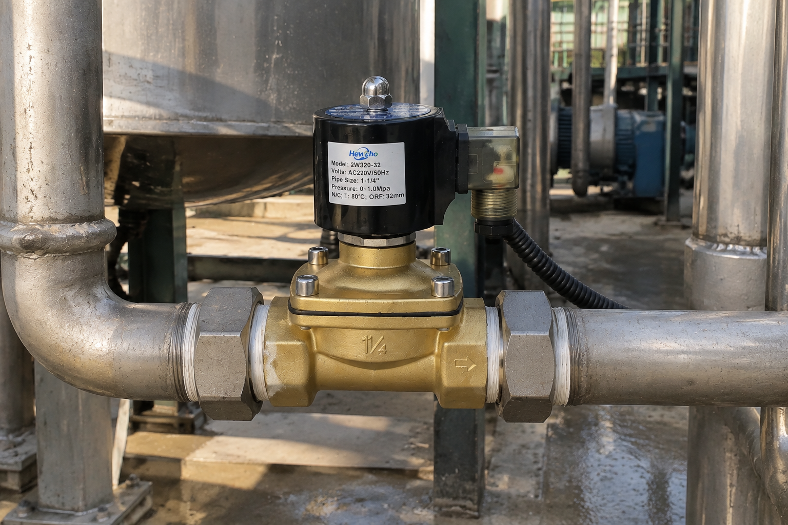
Reliable solenoid valve operation is built from consistent selection, clean installation, measured commissioning, and useful maintenance evidence. When the process team and maintenance team share the same information, the valve becomes a predictable part of the plant rather than an isolated source of interruption.

