
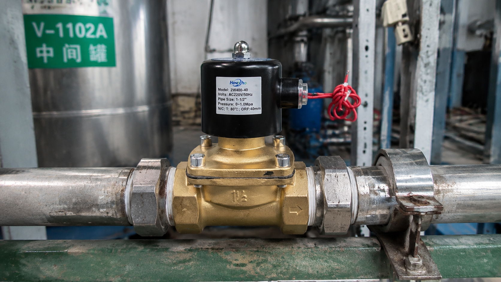
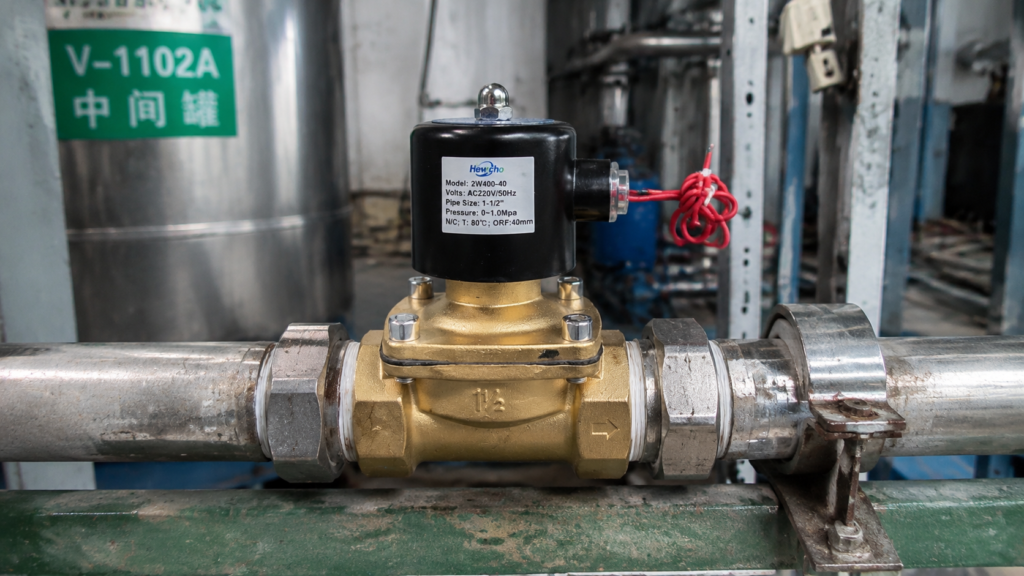
Yesterday, we investigated the tribological challenges of micro-silt accumulation and silt-lock, analyzing how annular pressure relief grooves and electropolished surfaces prevent mechanical plunger seizure. Today, we turn our attention to an equally critical boundary condition that dictates long-term electrical reliability in continuous-duty applications: Coil Thermal Management and Duty-Cycle Limitations.
In high-throughput process loops—such as continuous chemical dosing, automated manufacturing cooling lines, and power-generation auxiliary skids—2-way solenoid valves are frequently subjected to prolonged or permanent energization. When an electrical coil remains energized for extended periods, continuous Joule heating (I^2R) drives internal temperatures upward. If thermal dissipation is mismanaged, the insulation system breaks down, leading to catastrophic short circuits and unexpected plant shutdowns. Here is the engineering blueprint for managing solenoid thermal dynamics.
1. The Physics of Joule Heating and Thermal Equilibrium
When an electrical current (I) passes through the copper wire windings of a solenoid coil, electrical energy is continuously converted into thermal energy due to the conductor’s inherent resistance (R):
$$P_{\text{loss}} = I^2 R$$
As the temperature of the copper wire rises, its electrical resistance increases linearly according to the temperature coefficient of resistance (\alpha). This creates a compounding thermal loop: higher temperature increases resistance, which alters current draw and modifies magnetic flux thresholds.
At steady state, the internal heat generated by the copper windings must equal the heat dissipated to the ambient environment through convection, conduction, and radiation. If the ambient temperature spikes or the valve is enclosed in a poorly ventilated cabinet, the thermal equilibrium point shifts past the insulation’s maximum rated threshold, initiating thermal aging.
2. Understanding Insulation Classes and Temperature Ratings
To prevent premature coil failure, manufacturers categorize magnet wire insulation systems into strict international standards (IEC 60085 / NEMA ICS 1). Specifying the correct insulation class is critical for matching the valve to its operational environment:
| Insulation Class | Maximum Continuous Operating Temperature | Typical Application Threshold |
|---|---|---|
| Class B | 130^\circ\text{C} (266^\circ\text{F}) | Standard indoor automation, low ambient temperatures. |
| Class F | 155^\circ\text{C} (311^\circ\text{F}) | General industrial process loops, moderate ambient heat. |
| Class H | 180^\circ\text{C} (356^\circ\text{F}) | Heavy-duty industrial, steam service, outdoor sun-load skids. |
| Class N / 200 | 200^\circ\text{C} (392^\circ\text{F}) & Above | Extreme high-temperature media, close-coupled engine compartments. |
Exceeding these limits by even 10^\circ\text{C} cuts the lifespan of the polymer insulation matrix in half, according to the Arrhenius reaction rate principle.
3. Engineering Solutions: Combating Thermal Runaway
To ensure reliable, 100% continuous duty-cycle (100\% ED) performance without thermal degradation, advanced solenoid designs incorporate specific architectural enhancements:
Encapsulated Epoxy and Thermally Conductive Resins
Standard low-cost coils feature air pockets between windings, which act as thermal insulators and trap heat in the core. Premium industrial coils are vacuum-encapsulated in thermosetting epoxy resins infused with ceramic or quartz fillers. This solid matrix eliminates air gaps, dramatically increasing thermal conductivity (k) and allowing heat to migrate swiftly from the internal copper windings outward to the external metal housing and ambient air.
Electronic “Hit-and-Hold” Energy Management Circuits
For large, high-force direct-acting valves, the magnetic force required to pull the plunger open is significantly higher than the force required to hold it open.
- The Technology: Advanced coils incorporate integrated pulse-width modulation (PWM) or external electronic timing modules.
- The Thermal Benefit: The circuit delivers a high-amperage surge for the first 100\text{ ms} (the “hit” phase) to snap the valve open, then instantly drops the current by 50\% to 70\% for the duration of the cycle (the “hold” phase). By cutting the current during the holding phase, Joule heating (I^2R) drops exponentially, dropping internal coil temperatures by up to 30^\circ\text{C} and guaranteeing true 100\% continuous duty capability.
Technical Sourcing Specs for Thermally Demanding Loops
When compiling procurement guidelines for 2-way solenoid valves operating in high-ambient or continuous-energization environments, mandate these thermal design standards:
| Engineering Variable | Sourcing Requirement | Thermal Justification |
|---|---|---|
| Duty Cycle Rating | 100\% ED (Continuous Duty) | Certified for permanent energization without exceeding maximum thermal limits. |
| Coil Encapsulation | Vacuum-Cast Thermally Conductive Epoxy | Enhances convective and conductive heat transfer away from copper windings. |
| Thermal Protection | Integrated Auto-Reset Thermal Cutoff (TCO) | Physically breaks the circuit if ambient anomalies push temperatures past safety thresholds. |
Conclusion
Thermal management is the cornerstone of electrical longevity in fluid automation. Treating a solenoid coil as an infinite-duty component without verifying its insulation class or duty-cycle rating invites sudden coil burnout and costly downtime. By deploying vacuum-encapsulated heat-dissipating resins, utilizing electronic hit-and-hold drivers, and matching insulation classes (Class H/N) to your operational environment, you ensure that your 2-way solenoid valves deliver cool, reliable, and uninterrupted performance under the most punishing thermal loads.

