
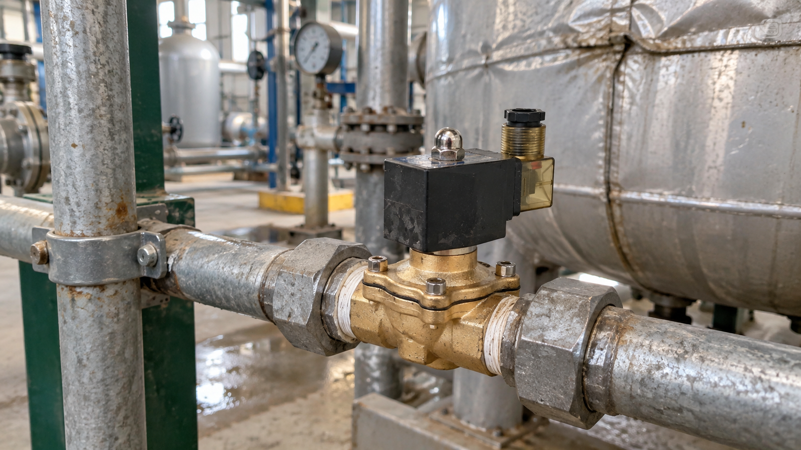
A repeatable selection workflow helps industrial teams connect a solenoid valve to the process it must serve. Instead of choosing from a catalogue by appearance or connection alone, the team can document the medium, pressure relationship, flow need, control state, materials, installation environment, and maintenance plan. This approach supports clear communication between process, piping, electrical, and operations personnel while keeping claims limited to verified requirements.
Reliable industrial fluid control begins before a valve is energized. Process teams need a clear picture of the medium, pressure relationship, control behavior, materials, and maintenance access that surround each installation. This practical readiness guide turns those considerations into an actionable review for operations, engineering, and maintenance personnel. It is intended to support careful decisions using verified process facts rather than assumptions about a component.
Maintenance is where a sound solenoid valve selection becomes dependable daily operation. Even when the original valve matches the medium and control duty, changing process conditions can introduce contamination, unstable pressure, loose wiring, or wear at connected equipment. A practical maintenance routine does not need to be complicated. It should help a team notice change early, test the correct function safely, and distinguish a valve problem from a wider piping or electrical problem.
Use the original duty as the maintenance baseline
Start with the intended service. Record the medium, expected cleanliness, normal inlet and downstream conditions, normal state, body and seal materials, electrical supply, and installation date. The catalogue provides options for common media including water, air, gas, oil, and steam-related duties, as well as different construction and material choices. Those facts are useful only if they remain connected to the actual installation. A concise equipment record lets a technician compare current behavior with the condition for which the valve was selected.
Update the record whenever the process changes. A new fluid, a different cleaning method, altered pump operation, or more frequent cycling may affect the valve even if the piping has not been rebuilt. The goal is not paperwork for its own sake. It is to prevent maintenance decisions based on assumptions that are no longer true. When a replacement is eventually needed, the record also helps the team preserve the necessary function rather than choosing only by external appearance.
Inspect the piping environment before isolating the valve
Many apparent valve faults originate in the surrounding line. Look first for leakage at joints, mechanical stress from unsupported piping, signs of corrosion, and evidence of debris entering the flow path. A filter or strainer upstream may need attention before the valve itself is disturbed. Deposits and particles can restrict passages or interfere with sealing surfaces, leading to slow response, incomplete closing, or unexpected flow. These symptoms can resemble an electrical failure, so the inspection should include both fluid and control conditions.
Review flow direction as well. The installed direction should agree with the marking on the valve. If the line has been modified, confirm that later piping work did not create a condition different from the original arrangement. Where the process allows, observe whether an upstream or downstream restriction changes the behavior. A valve should be assessed in the context of the pressure relationship it actually sees, especially when the system experiences pump starts, vessel filling, or intermittent low-flow periods.
Check electrical condition with the process safely controlled
The coil and electrical connection deserve regular visual inspection. Look for damaged insulation, loose connections, strain on cable entries, moisture exposure, or signs of overheating. Confirm that the available supply matches the coil fitted to the valve and that protective measures suit the installation environment. Do not treat an audible click as complete proof of operation. A coil may respond while a fluid-side issue prevents the intended process result.
During a controlled functional test, observe the valve while it is energized and again after it is de-energized. Compare the resulting flow with the documented normal state. The catalogue includes normally closed and normally open functions, so the unpowered condition must be clear to everyone involved. A valve that does not return to the intended position should trigger a review of electrical control, internal cleanliness, pressure conditions, and the wider process requirement. Safe isolation procedures must always take priority over a quick test.
Relate pressure behavior to valve construction
Direct-acting and pilot-operated constructions respond to pressure conditions in different ways. A maintenance inspection should therefore include the pressure relationship across the valve, not just an external visual check. If the process has changed from a stable condition to one with very low differential pressure or frequent fluctuations, a previously satisfactory installation may behave differently. Document the observed inlet and downstream conditions before deciding that the component itself has failed.
Unexpected response can also come from equipment beyond the valve. Pump transitions, closed downstream equipment, restricted piping, or a changed flow demand can alter the available conditions. A methodical technician asks what changed in the system, then tests that explanation where it is safe to do so. This approach reduces unnecessary replacements and provides better information when a valve does require service.
Keep materials and environment under review
Body materials in the catalogue include brass, stainless steel, and plastic options such as UPVC and CPVC. Seals, temperature, medium, and external atmosphere must be considered alongside the body construction. During inspections, look for changes that may indicate compatibility concerns, including external corrosion, cracking, hardened deposits, or leakage around joints. Do not assume that a material suitable for one duty remains suitable after a change in fluid, temperature, or cleaning practice.
Steam duties and exposed industrial locations deserve focused observation. Heat can affect nearby wiring and connected parts as well as the valve body. Outdoor, washdown, or corrosive environments may place additional demands on connections and enclosures. When the observed condition does not match the documented service, record the difference and seek a confirmed compatibility review rather than relying on a general impression.
Set maintenance intervals from actual conditions
There is no single maintenance interval that fits every installation. Set inspection frequency according to fluid cleanliness, cycling rate, temperature exposure, accessibility, and the consequence of an unplanned flow change. A basic route can include checking for leakage, reviewing filtration, examining wiring, confirming pipe support, and performing a functional test when process conditions permit. More demanding service may justify closer observation, while stable clean service may need less frequent intervention.
When a symptom appears, record it before changing components. Note whether the issue is continuous or intermittent, whether it occurs only during a particular process stage, and whether other equipment was operating at the time. This evidence makes troubleshooting more efficient and supports a better repair decision. It also helps distinguish a valve concern from a control signal, supply, or piping condition that happens to be visible at the same time.
Conclusion
Consistent solenoid valve operation comes from maintaining the full system around the valve. Keep the original duty visible, inspect the pipework and electrical connection, test the intended energized and unpowered behavior, and review pressure and material conditions when the process changes. A disciplined record and a simple condition-based routine provide a practical foundation for reliable industrial fluid control.

