
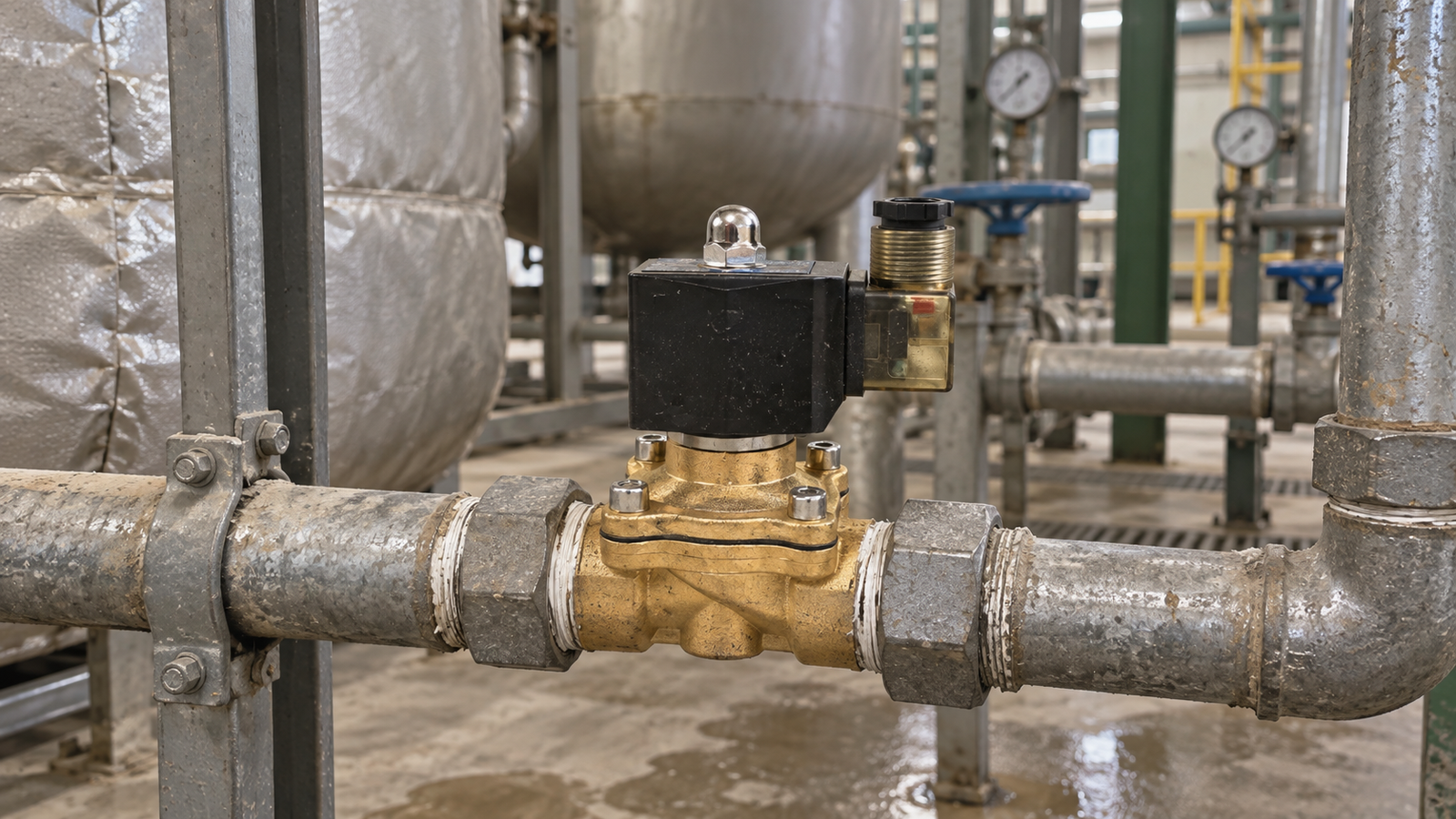
A solenoid valve can be a small component in a fluid system, yet its commissioning quality has a large effect on uptime, repeatability, and service effort. A reliable start-up process connects the valve to the real operating conditions instead of treating installation as a simple wiring task. Before a line is energized, the project team should confirm the process medium, pressure relationship, control philosophy, electrical supply, piping arrangement, and maintenance access. This discipline helps operators find problems early and creates a practical record for future service.
Define the process duty before selecting the valve
The first step is to describe what the valve must do in the process. Identify whether it will admit, isolate, drain, vent, or redirect a medium, and record how often the command will change. A valve that opens for short, regular cycles may face different demands from one that remains energized for long periods. Note the normal operating state and the safe state required when power is removed. For many control points, a normally closed arrangement is useful because the passage remains shut without an electrical command, but the correct state depends on the process risk and the overall control design.
Write the duty in plain language that can be understood by process, electrical, and maintenance teams. Include the expected flow direction, the upstream and downstream equipment, and any restrictions imposed by the piping layout. This shared description prevents a part from being chosen only by connection size or appearance.
Map the medium and material compatibility
Fluid compatibility should be treated as a complete system question. Record whether the medium is water, air, oil, an inert gas, a cleaning solution, or another process fluid. Then consider concentration, contamination, temperature, and the possibility of suspended particles. Body materials, sealing materials, and internal components must remain suitable for the medium over the expected operating range. A material that performs well with clean water may require a different review when the same line carries additives, detergents, or fine solids.
Cleanliness is equally important. Flush new piping before commissioning, remove cutting debris, and use a strainer when the process can carry particles that may interfere with the sealing surfaces. If the catalogue specifies a general material choice but the process fluid is unusual, treat the application as a compatibility review rather than assuming that a familiar material is automatically acceptable.
Match pressure, flow, and piping conditions
Pressure is not just a single number. Record the minimum and maximum inlet pressure, the pressure on the outlet side, and the differential pressure available when the valve must change state. Check whether the valve needs a pressure difference to operate correctly and whether the line can create a sudden pressure change when the passage opens. A control point that works well during a steady test may behave differently when pumps start, tanks empty, or downstream equipment changes demand.
Flow requirements should be described in process terms rather than guessed from pipe diameter. Determine the required flow rate, acceptable pressure loss, and the time allowed for opening or closing. Consider water hammer and trapped air, especially in long runs or vertical piping. Support the pipe so that the valve body is not carrying mechanical strain, and use fittings that allow the valve to be removed without dismantling an entire section of the line.
Confirm the electrical command and fail-safe behavior
Before wiring, verify the available voltage, frequency, current demand, connector arrangement, and control output. Compare the actual supply with the valve coil information and use suitable protection for the installation environment. Keep control wiring separate from sources of electrical noise where practical, and label both ends of each conductor. A clear label should identify the process function and the panel connection, not merely the physical location.
Test the behavior that operators will see during a power interruption. Confirm whether the valve closes, opens, or remains in its last commanded state according to the selected design. Interlocks, emergency stops, and manual overrides should be tested with the process in a safe condition. This is where a commissioning checklist adds value: it turns assumptions about the fail-safe state into an observable result.
Plan installation and service access
Install the valve in the orientation recommended for its construction and keep the surrounding area accessible. Leave enough clearance to inspect the coil, connector, body, seals, and nearby fittings. Protect the assembly from continuous vibration, flooding, excessive heat, and accidental impact. If the line is outdoors, review enclosure protection, drainage, and cable entry points before the first energization.
Use clean, compatible sealing practices on threaded connections and avoid applying excessive force to the body. The arrow or flow marking should agree with the piping design. After tightening, inspect the joint visually and perform a controlled leak check before introducing the full process load.
Commission gradually and record the results
Start with a dry or low-risk test when the process permits it. Check the electrical command, listen for the expected actuation, and observe whether the downstream equipment responds correctly. Then introduce the medium slowly while monitoring leakage, pressure, flow, and unusual noise. Operate the valve through several cycles and record the response time, the command state, and any visible vibration.
Document the final wiring, process conditions, inspection points, and test results. A short record should include the installation date, responsible technician, cleaning method, observed pressure range, and any follow-up action. Good records reduce guesswork when a similar control point is commissioned later.
Build a practical maintenance loop
Maintenance should follow the actual duty cycle. Inspect connections, cable entries, signs of leakage, and coil temperature at a frequency appropriate to the environment. Verify that strainers remain clean and that upstream piping has not introduced debris. If response becomes slow or inconsistent, compare the current pressure and electrical readings with the original commissioning record before replacing parts.
Keep a small set of approved seals, connectors, and cleaning materials available when the process is critical, but do not substitute components without checking material and electrical compatibility. A repeatable inspection routine, combined with clear records, usually prevents minor contamination or loose connections from becoming an extended shutdown.
Conclusion
Reliable solenoid valve service begins before the first command is sent. Define the duty, confirm material and pressure compatibility, verify the electrical behavior, install with service access, and commission in measured steps. When these actions are recorded in a simple checklist, the valve becomes part of a controlled operating system rather than an isolated component. The result is clearer troubleshooting, safer intervention, and more predictable performance across the life of the installation.

