
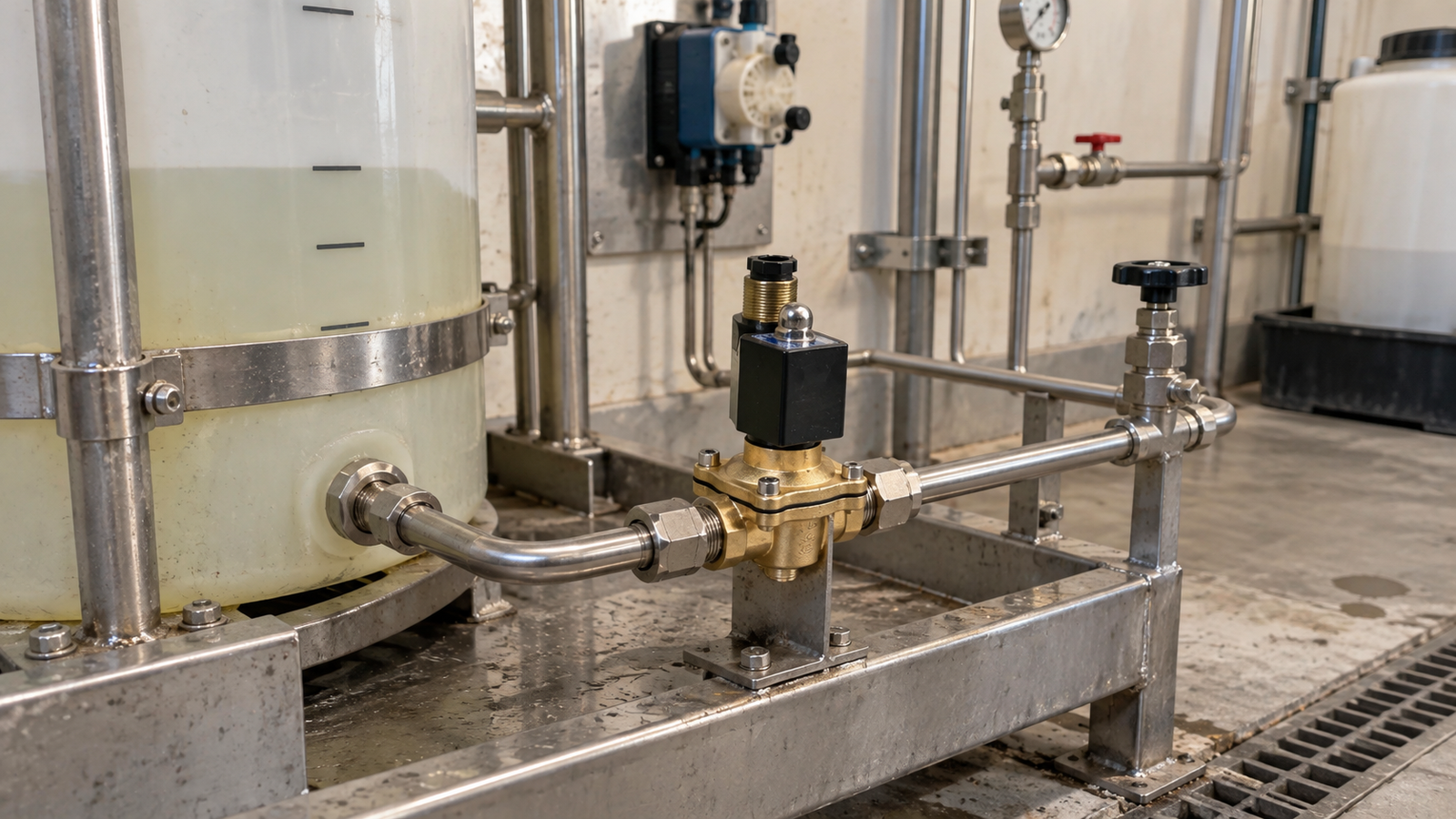
A solenoid valve is often selected for its simple control function, yet long-term reliability depends on much more than the first installation. In an industrial fluid system, the valve works with the medium, pipework, pressure conditions, electrical command, and operating environment. A practical maintenance plan connects all of these factors so that technicians can inspect the right items at the right time. The goal is not to replace parts too early, but to recognize the conditions that shorten service life and to correct them before they interrupt production.
Begin with the actual duty
The maintenance plan should start with a clear description of what the valve does. It may admit water, isolate compressed air, drain a line, vent a section, or control a cleaning fluid. Record how often the valve changes state, how long it remains energized, and what condition it should take when power is removed. A valve that cycles many times per shift may need a different inspection rhythm from one that operates only during start-up or shutdown.
This duty statement should be practical and easy to read. Include the upstream and downstream equipment, the normal flow direction, the usual pressure range, and the surrounding environment. When this information is stored with the maintenance record, a technician can compare current symptoms with the original purpose of the installation rather than guessing from location alone.
Watch the medium and cleanliness
Fluid compatibility is central to maintenance planning. Water, air, oil, cleaning liquid, and other industrial media can affect sealing surfaces, body materials, and internal movement in different ways. Temperature, concentration, additives, and contamination should be reviewed as part of the routine. Even when the medium itself is suitable, particles from pipe cutting, corrosion, or upstream work can create leakage, slow response, or inconsistent sealing.
A good plan includes checks for strainers, flushing points, and visible contamination. If a line is opened for unrelated work, the valve should not be forgotten when the system is returned to service. Cleaning debris from the pipeline before operation is often faster than diagnosing a control problem after particles have reached the valve seat. Where the fluid is unusual, the maintenance record should state the compatibility assumptions that were reviewed.
Track pressure and flow conditions
Pressure changes are a common source of confusing symptoms. Record the normal inlet pressure, outlet pressure, and expected pressure difference across the valve. If the valve depends on certain pressure conditions to operate correctly, the inspection routine should confirm that the system still provides those conditions. A pump change, blocked filter, partially closed manual valve, or modified downstream branch can change the pressure relationship without any change to the valve itself.
Flow behavior should also be observed during inspections. Look for noise, vibration, delayed response, or signs of water hammer. These symptoms may point to trapped air, excessive flow velocity, weak pipe support, or a sudden change in demand. Maintenance teams should avoid treating every symptom as a failed component until the surrounding fluid conditions have been checked.
Include the electrical side
Because a solenoid valve is an electrically operated device, the maintenance plan must include wiring and control checks. Confirm the supply voltage, connector condition, cable entry, grounding practice, and control output. Loose terminals, moisture at a connector, damaged insulation, or electrical noise can all appear as intermittent valve operation. A clean mechanical assembly cannot perform reliably if the command signal is unstable.
Labels are a small but important part of the system. Each cable should identify the process function and control connection, not only the physical location. When a technician is working under time pressure, clear labeling reduces the risk of testing the wrong circuit or replacing the wrong component. If a connector is opened during service, inspect the seal and seating before returning the line to operation.
Plan inspections around the environment
The same valve can face very different service conditions depending on where it is installed. Areas with heat, washdown, outdoor exposure, chemical mist, vibration, or dust may require more frequent inspection. Check for corrosion, loose mounting, damaged cable glands, and signs that liquid has reached the coil or connector. Confirm that the installation remains accessible and that nearby equipment has not made inspection difficult.
Mechanical strain should also be reviewed. Pipework should be supported so the valve body is not carrying loads from misalignment or vibration. During maintenance, look for fittings that have been overtightened or sealant that has entered the flow path. Good installation practice protects the valve, but ongoing inspection confirms that the original conditions have not changed.
Create a useful commissioning baseline
A maintenance plan is stronger when it starts with a commissioning baseline. During start-up, record the pressure range, electrical supply, response behavior, leak check result, installation orientation, and any cleaning steps completed before operation. This information becomes the reference point for future troubleshooting. Without it, technicians may only know that the valve worked at some earlier date, which is not enough to identify what has changed.
Baseline data does not need to be complicated. A short form with measured values, observations, and responsible personnel is usually enough. The key is consistency. If each similar control point is documented in the same way, maintenance teams can compare installations and find patterns across the plant.
Use symptoms to guide action
When operation becomes slow, noisy, or inconsistent, start with observation before replacement. Check whether the electrical command arrives at the correct time. Confirm the actual pressure conditions. Inspect the connector and nearby wiring. Look for contamination in the line or strainer. Verify that manual isolation valves are fully open and that downstream equipment is not creating a restriction.
This step-by-step approach prevents unnecessary replacement and helps identify the true cause of the fault. If a component is replaced without checking the surrounding system, the same symptom may return quickly. A reliable maintenance plan treats the valve as part of the full fluid-control circuit.
Keep records that technicians will use
Maintenance records should be short, consistent, and easy to retrieve. Record the inspection date, operating condition, cleaning action, measured values, and any follow-up. Note changes to piping, wiring, medium, or operating schedule. These details help the next technician understand whether a problem is new, recurring, or linked to another change in the system.
Conclusion
Good solenoid valve maintenance is practical, repeatable, and connected to real operating conditions. Define the duty, monitor the medium, track pressure and flow, inspect the electrical command, and adjust the routine for the environment. When commissioning data and service records are kept together, the valve becomes easier to support throughout its working life. The result is fewer avoidable interruptions and a clearer path when troubleshooting is required.

