
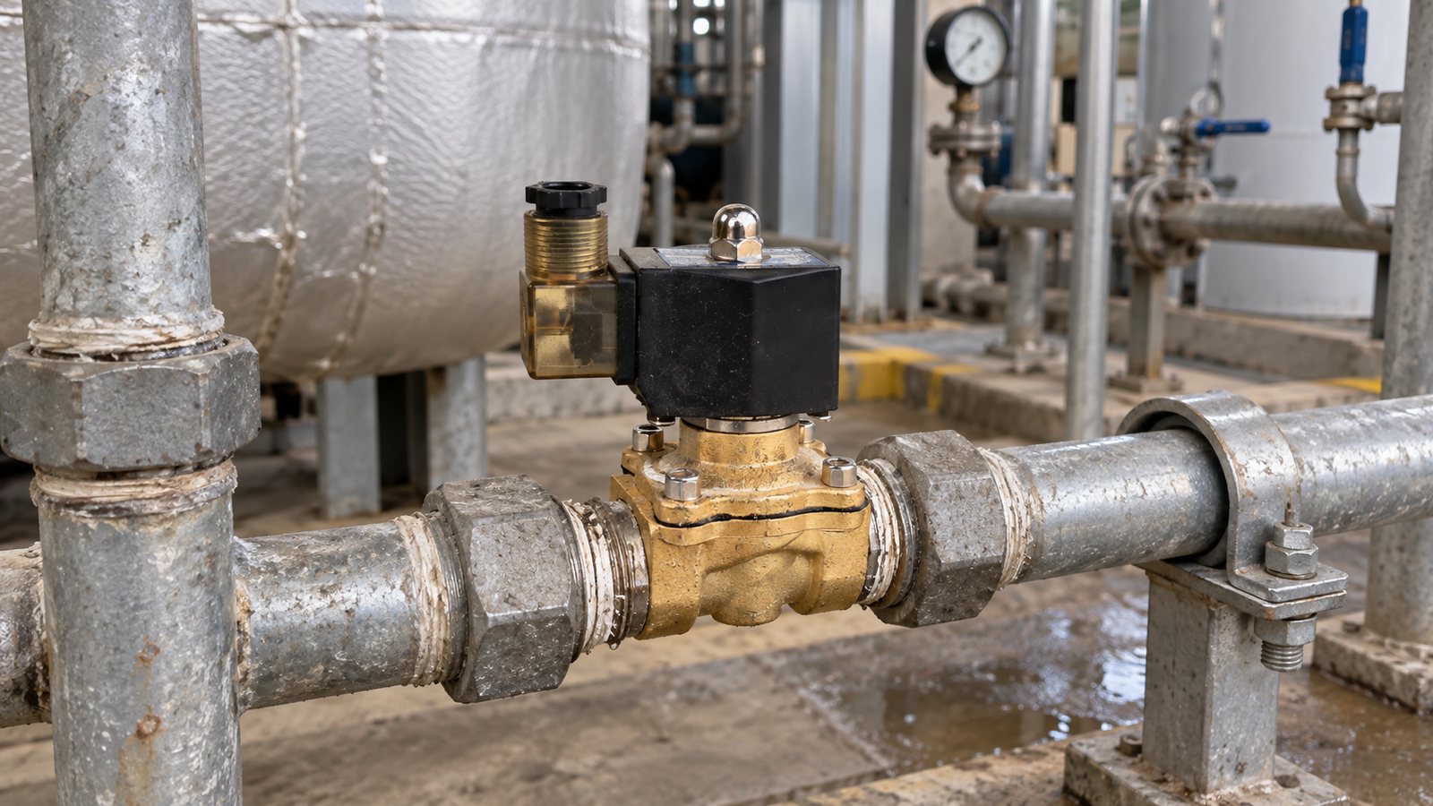
Reliable solenoid valve operation is the result of coordinated decisions, not a single installation step. The valve must match the process medium, pressure conditions, electrical command, piping arrangement, and service environment. When these factors are reviewed together, a control point is more likely to start cleanly, respond consistently, and remain easy to inspect. A practical framework also gives operators and maintenance teams a common way to discuss symptoms before a small issue becomes a production interruption.
Define the function in process language
Begin by describing the task the valve performs in the system. It may admit a medium, isolate a section, drain a vessel, vent a line, or direct flow toward another piece of equipment. Record how often the valve changes state, how long it may remain energized, and what should happen if electrical power is lost. The required safe state belongs to the process design, so it should be agreed by process and controls personnel rather than assumed from a familiar installation.
A short duty statement should include the upstream and downstream equipment, the intended flow direction, the normal operating state, and the expected response time. This information prevents a component from being selected only by pipe connection or by visual similarity. It also makes later troubleshooting more focused because the team can compare actual behavior with a clearly documented purpose.
Review the medium and construction materials
Material compatibility must reflect the real fluid, not only its common name. Record concentration, temperature, cleanliness, additives, and the possibility of suspended particles. Water, compressed air, oil, cleaning liquid, and process chemicals can place different demands on the body, seals, and internal moving parts. The chosen construction should remain suitable during start-up, normal operation, shutdown, and any cleaning cycle that is part of the process.
Cleanliness deserves its own check. Flush new piping before commissioning, remove thread-cutting debris, and consider a strainer when particles may enter the line. Contamination can affect sealing surfaces and make a mechanical restriction appear to be an electrical fault. When a fluid is unusual or its concentration changes, record the compatibility assumptions and identify who approved them. That record is useful when a future technician sees a symptom that does not match ordinary service experience.
Map pressure, flow, and dynamic behavior
Pressure should be measured as a relationship across the control point. Capture the minimum and maximum inlet pressure, the outlet pressure, and the differential pressure available when the valve is expected to operate. Conditions can change when a pump starts, a tank level falls, or another branch opens. A valve that operates correctly during a steady test may respond differently during a transition, so the commissioning plan should include the most important changes in process demand.
Define flow in terms of the equipment requirement. Estimate the required flow rate, acceptable pressure loss, and the time allowed for opening or closing. Consider trapped air, long pipe runs, vertical sections, and the possibility of water hammer. Nearby pipework should be supported so that mechanical loads are not transferred to the valve body. Service-friendly unions or isolation points are also valuable because they allow inspection or replacement without dismantling an entire line.
Verify the electrical command and safe response
Before wiring, confirm the available voltage, frequency, current demand, connector arrangement, and control output. Compare the supply with the coil information and use suitable protection for the environment. Keep control wiring away from strong sources of electrical noise where practical, and label both ends of every conductor. A useful label identifies the process function and panel connection, not only a location that may change during a later modification.
Power-loss behavior should be tested deliberately. Confirm whether the valve closes, opens, or remains in its last commanded state according to the selected design. Interlocks, emergency stops, and manual overrides should be checked with the process in a safe condition. A written checklist turns an assumption about fail-safe behavior into a result that can be observed, signed, and repeated on another shift.
Install with inspection in mind
Follow the recommended installation orientation and keep the assembly accessible. Leave enough clearance to inspect the coil, connector, body, seals, and nearby fittings. Protect the valve from continuous vibration, flooding, excessive heat, and accidental impact. Outdoor locations require an additional review of enclosure protection, drainage, cable entry, and the effect of changing weather conditions.
Use clean, compatible sealing practices on threaded connections and avoid applying excessive force to the body. Check that the flow marking agrees with the piping plan. After tightening, inspect every joint and complete a controlled leak check before applying the full process load. Good access is not merely convenient; it reduces the chance that a small inspection will be postponed until a leak or loose connector causes a shutdown.
Commission in stages and capture a baseline
When the process allows it, start with a dry or low-risk test. Confirm the electrical command, listen for the expected actuation, and observe the response of connected equipment. Introduce the medium slowly while monitoring leakage, pressure, flow, and unusual noise. Operate the valve through repeated cycles and record the command state, response time, and visible vibration.
One successful cycle is not enough to establish reliability. Repetition can reveal trapped air, unstable pressure, loose wiring, or control logic that fails only after a particular sequence. Record the actual conditions during testing so that future troubleshooting has a useful baseline. A note such as “working normally” is much less valuable than a record of pressure, temperature, command state, and observed response.
Build a maintenance loop around the duty
Maintenance frequency should reflect the duty cycle and the surrounding environment. Inspect cable entries, connectors, signs of leakage, coil temperature, pipe supports, and nearby fittings. Verify that strainers remain clean and that upstream work has not introduced debris. If operation becomes slow or inconsistent, compare current pressure and electrical readings with the commissioning record before replacing a component.
Keep approved seals, connectors, and cleaning materials available for critical lines, but do not substitute parts without confirming material and electrical compatibility. A short service record should include the inspection date, observed condition, cleaning action, and any follow-up. Consistent records help different technicians follow the same standard and make recurring problems easier to recognize.
Use operating records to improve future work
The commissioning record should remain useful after the start-up project is complete. Save the process duty, pressure range, wiring arrangement, installation orientation, test observations, and maintenance interval. When a new control point is designed, this information helps the team ask better questions about the medium, safe state, service clearance, and likely contamination sources. It also creates a shared vocabulary between design, operations, and maintenance.
Conclusion
Reliable solenoid valve operation is built through preparation, verification, and disciplined follow-up. Define the duty in process language, confirm material and pressure compatibility, verify the electrical command, install for access, commission in measured stages, and preserve a clear baseline. These actions reduce avoidable faults and make genuine process changes easier to identify. The result is more predictable control for operators and a more efficient path for maintenance teams when attention is required.

