
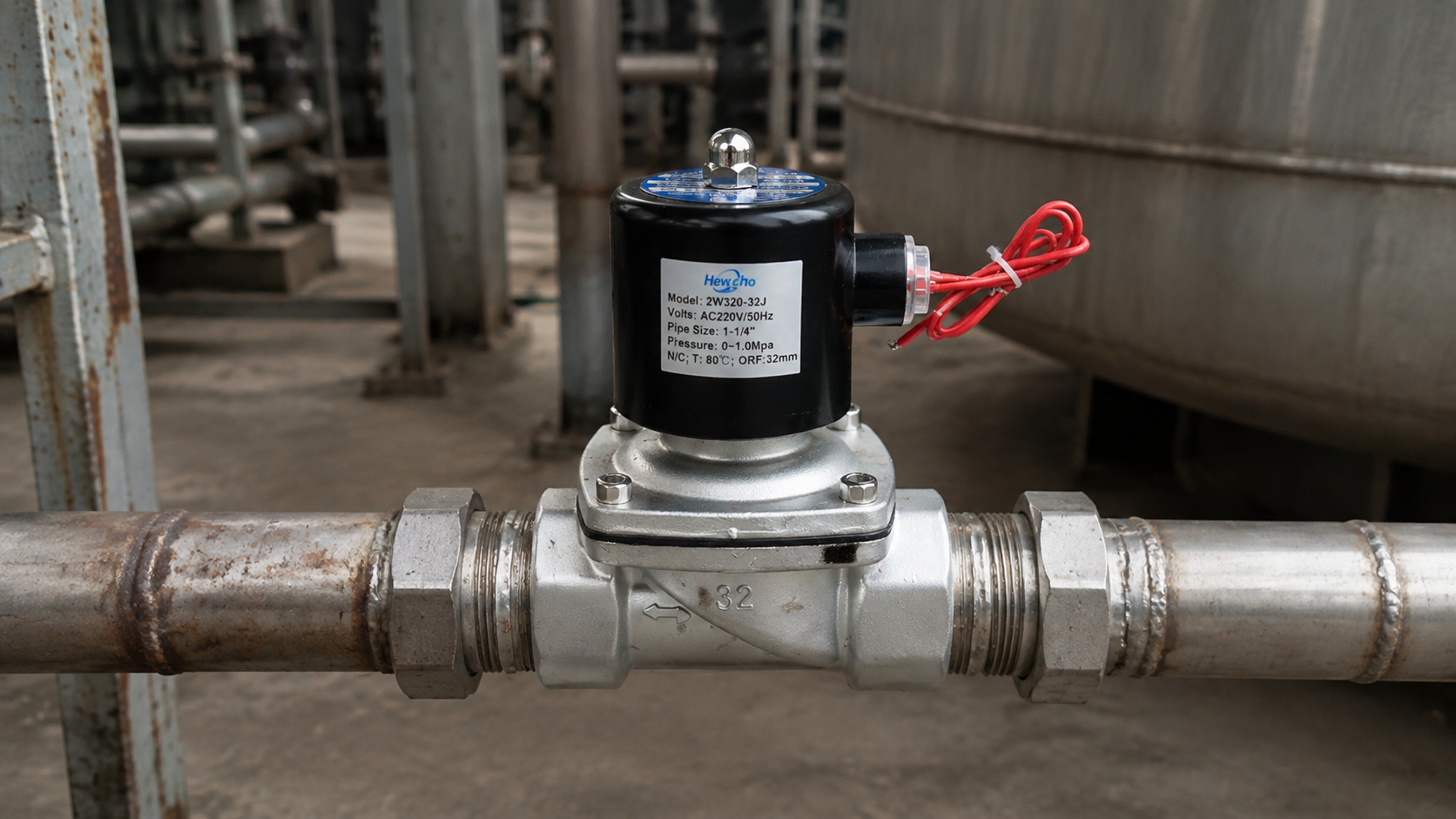
Industrial solenoid valves are compact devices, but they sit at the intersection of process conditions, electrical control and mechanical installation. The catalogue used for this guide covers choices for media including air, gas, water, steam, liquid and light oil, together with different body materials, sealing options, connections and operating principles. That variety is useful only when it is matched to real operating information. A valve that performs well in one line can be unsuitable in another if pressure, temperature, cleanliness or the required response to power loss is different.
Build a complete operating profile
Start with a written description of the duty. Identify the medium, the normal and maximum pressure, the temperature range, the desired flow and the expected operating cycle. Include start-up, shutdown, cleaning and low-load conditions rather than recording only the normal production point. Viscosity, suspended particles, chemical concentration and the presence of oil can change the requirements for the flow path, body and seal. A clear duty description gives procurement, engineering and maintenance teams the same basis for reviewing a proposed valve.
The required valve state when power is removed is equally important. The process may need the line to remain closed for isolation, or open to protect equipment and maintain a safe condition. Confirm this requirement with the process owner before ordering. It is easy to focus on connection size and coil supply while overlooking the position that matters most during an interruption. A documented requirement avoids a mismatch between the control system and the physical response needed by the process.
Assess pressure conditions over time
The catalogue distinguishes direct-acting and pilot-operated constructions. Direct action uses electromagnetic force at the valve seat and can be appropriate where operation at zero differential pressure is needed. Pilot operation uses pressure from the process fluid together with an internal pilot function. It can suit duties with larger flow requirements, but it depends on the process providing the required pressure difference. The operating principle should therefore be selected from the actual pressure profile, not from nominal pipe size alone.
Review what happens during start-up, low production rates, bypass operation and shutdown. At those moments, inlet and outlet pressure can become similar even though the normal pressure appears adequate. If a valve depends on a pressure difference, this can affect its ability to open or close as intended. Use commissioning records, trend data and a simple process drawing to test the assumption. When a problem occurs, this information also helps separate a valve fault from a condition created by another part of the system.
Select wetted materials for the real duty
Body and seal selection should be considered together. The catalogue offers brass, stainless-steel and plastic body choices, as well as several common sealing materials. Choose the body with the process medium, temperature, external environment and corrosion exposure in mind. Then choose the seal around the actual fluid, including cleaning chemicals and occasional upset conditions. A seal that is suitable for hot water or steam may not be suitable for an oil-containing medium. Broad compatibility statements are a starting point, not a substitute for checking the complete duty.
Record the material assumptions in the purchase specification and maintenance file. If the fluid, concentration, cleaning method or temperature changes, revisit the review rather than assuming the installed equipment remains suitable. Small changes can increase friction, shorten seal life or introduce corrosion before any visible leakage appears. Keeping a clear record also helps a replacement decision remain consistent with the process requirements instead of relying on an incomplete previous description.
Prepare the line for clean, safe service
Clean pipework protects the valve internally. Flush new or modified lines before installation to remove scale, welding debris, thread compound and loose particles. Contamination can obstruct narrow passages or stop a valve seat from sealing correctly. Where normal service may carry solids, use suitable upstream filtration and include its inspection in the maintenance plan. This is particularly important after construction, repairs or piping changes, when the risk of debris is higher.
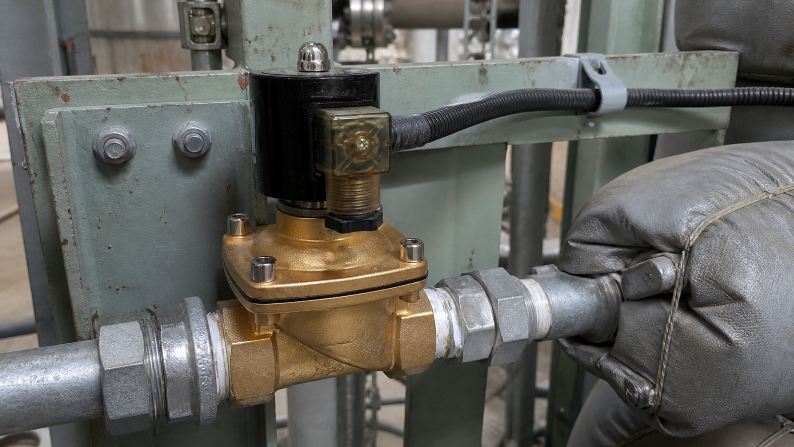
Mount the valve where technicians can isolate, inspect and replace it safely. Leave clearance for the electrical connector, pipe fittings and service tools. Support nearby pipework so that weight and vibration are not transferred to the body. Follow the marked flow direction for the selected configuration and avoid layouts that collect debris at the inlet. For hot-fluid and steam duties, consider heat exposure, insulation boundaries and the time needed for equipment to cool before maintenance begins. Good access makes routine checks more likely to be completed properly.
Confirm electrical performance at commissioning
The catalogue lists both alternating-current and direct-current coil options. Confirm that the supply at the installation point matches the selected voltage and, where relevant, frequency. Inspect terminals, cable entries, strain relief and protective earthing according to site practice. Damaged insulation, loose connectors and poor cable routing can cause intermittent operation that resembles a mechanical fault. Label the control circuit and isolation point so that maintenance staff can trace a command path and work safely.
Commission the valve through the same control logic used in normal service. Check the response at start-up, during ordinary operation and after power is removed. Record the observed response, relevant process pressure and the state achieved by the valve. This creates a useful baseline for later troubleshooting. It also confirms that the mechanical installation, electrical connection and control sequence operate together rather than being tested as separate assumptions.
Turn operating evidence into maintenance action
Routine inspections can be simple, but they should be consistent. Look for external leakage, corrosion, loose fittings, damaged connectors and signs of overheating. Listen for changes in operating sound and compare valve response with the control command. Slow response, frequent cycling or unexpected leakage can arise from contamination, unsuitable conditions, worn parts or an electrical issue. Investigate the cause instead of repeatedly resetting a controller or replacing a component without evidence.
When service is necessary, isolate and depressurize the line, then allow hot equipment to cool. Keep exposed ports clean during disassembly and replace sealing components only with materials verified for the duty. After reassembly, perform controlled leak and function checks before returning the line to operation. Record the condition found, work completed and any process changes. Over time, these observations reveal patterns that help teams refine maintenance intervals and prevent repeat failures.
Conclusion
Reliable solenoid-valve operation comes from disciplined selection, clean installation, correct electrical work and evidence-based maintenance. Define the medium and operating envelope, confirm pressure conditions, select materials deliberately and provide access for inspection. Treating process data and maintenance observations as part of the same decision helps teams use catalogue information responsibly and supports more predictable operation throughout the life of the equipment.

