
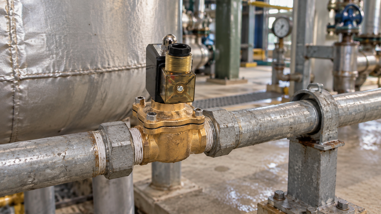
Reliable fluid control depends on many small decisions made before a valve is energized. A solenoid valve may be compact, but its performance is influenced by the medium, pressure conditions, electrical command, piping layout, installation environment, and maintenance routine around it. When these factors are reviewed together, the result is a control point that starts consistently, responds predictably, and gives maintenance teams useful information when a problem appears.
Start with the real process duty
The best starting point is a clear description of the task the valve must perform. Record whether the valve will admit, isolate, drain, vent, or redirect a medium. Note how often it will change state, how long it may remain energized, and what should happen when electrical power is removed. A normally closed arrangement can be useful when the passage should remain shut until a command is present, but the safe state must always be decided from the process risk rather than from habit.
Describe the duty in language that process, piping, electrical, and operations teams can all understand. Include the equipment upstream and downstream, the intended flow direction, and the expected operating schedule. This simple document prevents a component from being selected only by connection size or by a visual resemblance to another installation.
Check the medium and material compatibility
Fluid compatibility is more than asking whether the body material looks suitable. Identify the actual medium, its concentration, temperature, cleanliness, and any additives that may be present. Water, compressed air, oil, cleaning liquid, and process chemicals can place different demands on body materials, seals, and internal parts. The correct material choice should remain stable across the full operating range, including start-up, shutdown, and cleaning cycles.
Cleanliness deserves equal attention. Flush new piping before the first test, remove cutting debris, and consider a strainer when particles may enter the line. Fine contamination can interfere with sealing surfaces and can make an electrical problem appear to be a mechanical one. When the fluid is unusual or the process contains additives, treat the application as a compatibility review and record the assumptions that were checked.
Understand pressure and flow behavior
Pressure should be mapped across the entire control point. Record the minimum and maximum inlet pressure, the outlet pressure, and the differential pressure available when the valve must operate. A valve may behave differently when pumps start, tanks empty, or downstream demand changes. Check whether the construction requires a pressure relationship to change state and whether the process can create a sudden pressure surge when the passage opens or closes.
Flow requirements should be defined in process terms. Determine the required flow rate, acceptable pressure loss, and the response time allowed by the equipment. Consider trapped air, long vertical runs, and the possibility of water hammer. Support nearby piping so the valve body is not exposed to mechanical strain, and provide unions or other service-friendly connections where a future replacement may be needed.
Verify the electrical command
Before wiring, confirm the available voltage, frequency, current demand, connector arrangement, and control output. Compare the actual supply with the coil information and use appropriate protection for the environment. Keep control wiring clear of strong sources of electrical noise where practical, and label both ends of each conductor. A useful label identifies the process function and panel connection instead of only naming a physical location.
Test the behavior during a power interruption. Confirm whether the valve closes, opens, or remains in its last commanded state according to the chosen design. Interlocks, emergency stops, and manual overrides should be tested with the process in a safe condition. A commissioning checklist is valuable here because it turns an assumed fail-safe action into an observable result that can be reviewed later.
Install for inspection and service
Follow the recommended installation orientation and keep the surrounding area accessible. Leave enough clearance to inspect the coil, connector, body, seals, and nearby fittings. Protect the assembly from continuous vibration, flooding, excessive heat, and accidental impact. Outdoor installations also require a review of enclosure protection, drainage, and cable entry points before the first energization.
Use clean and compatible sealing practices on threaded connections, and avoid applying excessive force to the body. Confirm that the flow marking agrees with the piping plan. After tightening, inspect each joint and perform a controlled leak check before introducing the full process load. Good access reduces the temptation to postpone small inspections until a minor leak becomes a shutdown.
Commission in measured steps
When the process permits, begin with a dry or low-risk test. Check the electrical command, listen for the expected actuation, and observe whether the downstream equipment responds correctly. Introduce the medium slowly while monitoring leakage, pressure, flow, and unusual noise. Operate the valve through several cycles and record the response, command state, and any visible vibration.
Do not rely on a single successful cycle. Repeated operation reveals loose connections, trapped air, unstable pressure, and control logic that only fails under a particular sequence. Record the actual operating conditions during the test so that later troubleshooting has a reliable baseline instead of a general statement that the installation was working.
Create a maintenance routine
Maintenance should reflect the real duty cycle and environment. Inspect cable entries, connectors, signs of leakage, coil temperature, and nearby supports at a frequency appropriate to the installation. Verify that strainers remain clean and that upstream work has not introduced debris. If the response becomes slow or inconsistent, compare current pressure and electrical readings with the original commissioning record before replacing components.
Keep approved seals, connectors, and cleaning materials available when the process is critical, but never substitute parts without checking material and electrical compatibility. A short service record should include the inspection date, observed condition, cleaning action, and any follow-up. Consistent records make recurring issues easier to identify and help different technicians follow the same standard.
Use records to improve future projects
The commissioning record should become a practical reference for similar control points. Save the process duty, pressure range, wiring arrangement, installation orientation, test observations, and maintenance interval. When a new line is designed, this information helps the team ask better questions about the medium, the safe state, and the access required for service. It also creates a common vocabulary between the people who design, operate, and maintain the system.
Conclusion
Solenoid valve reliability is built through preparation rather than through a single hardware choice. Define the duty, verify medium and pressure compatibility, confirm the electrical command, install with service access, commission gradually, and keep useful records. These steps reduce avoidable faults and make genuine process changes easier to recognize. A disciplined approach gives operators more predictable control and gives maintenance teams a clear path when the installation needs attention.

