
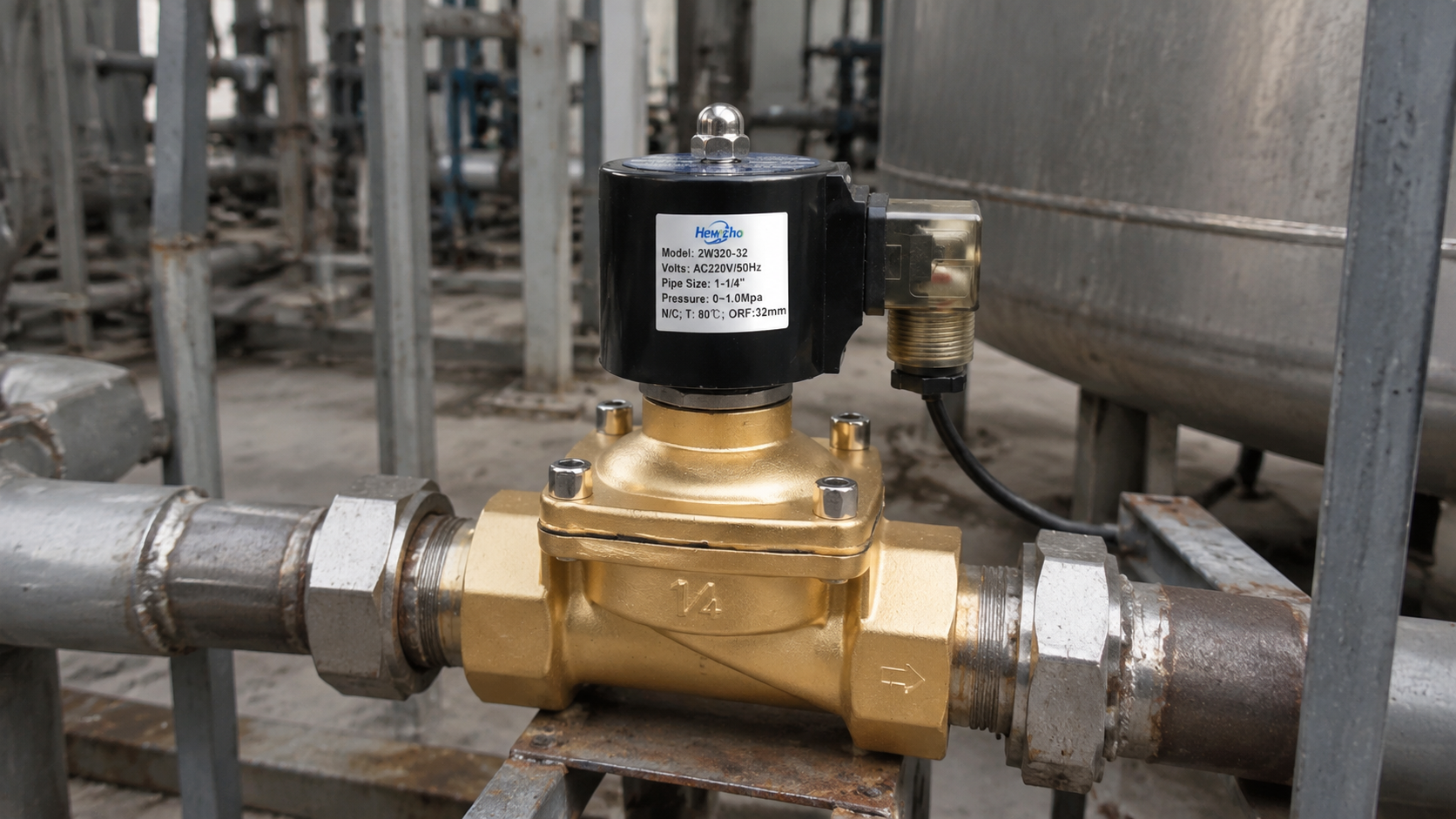
Yesterday, we discussed the digital twin framework and how remote telemetry tracks coil impedance, actuation latency, and power signatures to predict remaining useful life. Today, we turn our attention from data telemetry down to the physical electrical interface, examining a silent threat that can corrupt PLC logic networks and destroy solid-state controllers: Electromagnetic Interference (EMI) and Inductive Kickback in 2-Way Solenoid Valve Coils.
In dense industrial automation panels—such as multi-valve pneumatic manifolds, high-speed automated packaging lines, and hydraulic valve stands—dozens of 2-way solenoid valves switch simultaneously. Every time a DC or AC solenoid coil is de-energized, the collapsing magnetic field induces a violent high-voltage spike back into the control wiring. If left unmanaged, this transient energy generates severe EMI and can weld solid-state relay outputs shut or burn out low-voltage input/output (I/O) cards.
1. The Physics of Inductive Flyback (Kickback)
A solenoid valve coil is fundamentally an inductor. When the coil is energized, electrical energy is stored within its magnetic core as a magnetic field. According to Faraday’s Law of Induction, when the control switch opens and current is abruptly interrupted, the magnetic field collapses rapidly, attempting to maintain the current flow.
The resulting induced voltage transient (\nu_{L}) is governed by the core equation:
$$v_{L} = -L \frac{di}{dt}$$
Where:
- L is the inductance of the copper coil.
- di/dt is the near-instantaneous rate of change of current as the circuit breaks.
Because the change in time (\Delta t) during a sudden switch-off is measured in microseconds, the resulting voltage spike can reach amplitudes of 500\text{ V to over } 1,500\text{ V} on a standard 24\text{ VDC} control circuit. This high-frequency electrical arc radiates electromagnetic waves (EMI) across nearby signal cables and back-feeds destructive voltage spikes directly into the control architecture.
2. Transient Suppression Topography: Choosing the Right Protection
To prevent inductive flyback from degrading control system reliability, engineers integrate specific suppression networks directly across the coil terminals or inside the DIN-connector plug.
Flywheel Diodes (For DC Coils)
For DC-powered 2-way solenoids, a standard freewheeling diode (flyback diode) is wired in parallel (reverse-biased) across the coil terminals. When the circuit opens, the diode provides a safe, closed-loop local path for the collapsing magnetic energy to circulate and dissipate harmlessly through the copper winding resistance, effectively clamping the voltage spike to the diode’s forward drop (\approx 0.7\text{ V}).
Metal Oxide Varistors (MOVs) and Transient Voltage Suppressors (TVS)
For AC-powered solenoids (where standard diodes cannot be used), engineers utilize MOVs or bi-directional TVS diodes.
- The Mechanism: An MOV remains in a high-impedance (insulating) state during normal operation. When the voltage spike exceeds the clamping threshold, the MOV instantaneously switches to a low-impedance state, absorbing the transient energy and clipping the peak voltage to a safe level before it can reach the PLC output card.
3. Physical Wiring Architecture and Shielding Best Practices
Suppressing the voltage spike at the coil is only the first layer of defense. In high-density industrial environments, system layout dictates electromagnetic immunity:
- Twisted-Pair Cabling: Power and control leads running to 2-way solenoid valves should utilize twisted-pair wires. This geometry ensures that external magnetic flux fields induce equal and opposite voltages in the twisted conductors, effectively canceling out common-mode noise.
- Physical Segregation of Conductor Trays: High-voltage AC/DC power lines feeding solenoid coils must never share the same wire raceway or cable tray as low-voltage analog instrumentation (4-20\text{ mA}) or digital communication networks (EtherCAT, Profinet). A minimum physical separation of 300\text{ mm} (or an earthed metallic divider plate) must be maintained to prevent inductive cross-talk.
Technical Sourcing Specs for Electrical Protection
When compiling procurement specifications for industrial 2-way solenoid valves operating in noise-sensitive or high-switching-frequency environments, mandate these electrical standards:
| Performance Metric | Sourcing Requirement | Electrical Justification |
|---|---|---|
| Integrated Suppression | DIN-Plug with Built-In LED and MOV / Diode | Clamps inductive kickback locally at the coil, protecting PLC output cards from high-voltage spikes. |
| Coil Insulation Rating | Class H Molded Housing with Dielectric Isolation | Withstands high-potential testing and prevents internal arc-over during transient events. |
| Connector Sealing | IP65 / IP67 DIN 43650 Form A | Ensures moisture and corrosive vapor ingress cannot short-circuit the suppression network. |
Conclusion
Electrical resilience is just as critical to 2-way solenoid valve longevity as metallurgical and tribological design. By understanding the physics of inductive flyback and implementing localized suppression networks—such as flywheel diodes for DC systems and MOVs for AC loops—you eliminate destructive voltage transients at their source. This disciplined approach to electrical engineering protects your automation network, ensures noise-free signal integrity, and prevents premature relay failure across your entire fluid control infrastructure.

